Renesas Partners with Indian Government to Drive Innovation Through Startups and Industry-Academia Collaboration, Strengthening India’s Semiconductor Ecosystem
  Renesas Electronics Corporation (TSE:6723), a premier supplier of advanced semiconductor solutions, today announced its partnership with the Ministry of Electronics & Information Technology (MeitY), Government of India, to support local startups and academic institutions in the field of VLSI and embedded semiconductor systems. Renesas also celebrated the expansion of its offices in Bengaluru and Noida to accommodateits growing R&D teams, with the inauguration ceremonies held today. This strategic move underscores Renesas’ commitment to innovation and excellence in India and aims to drive continued growth in the region.  Renesas and the Centre for Development of Advanced Computing (C-DAC), an autonomous scientific society of MeitY, today signed and exchanged two Memoranda of Understanding (MOUs) under the MeitY Chips to Startup (C2S) programme (Note). These MOUs focus on 1) Supporting local startups by enabling them to drive technological advancement andpromote local manufacturing in alignment with the Make in India initiative; and 2) Enhancing industry-academia collaboration by fostering an innovative, product-focused mindset among students.  Shri Ashwini Vaishnaw, Minister for Railways, Information & Broadcasting, and Electronics & Information Technology, Government of India; along with Malini Narayanamoorthi, India Country Manager and VP, MID Engineering, Analog & Connectivity Group at Renesas; and Rea Callendar, Head of Platform Adoption and Ecosystem Enablement at Altium, which joined forces with Renesas in August 2024, attended the celebration at the Noida office. Hidetoshi Shibata, CEO of Renesas, also joined virtually, underscoring the global significance of this milestone.  India is a key market for Renesas, offering significant growth potential and access to a highly skilled talent pool. Renesas is committed to deepening its partnerships with local companies, startups, and universities, with the target to generate over 10 percent of itsglobal revenue from the Indian market by 2030. Recent collaborations include the OSAT factory project with CG Power and Stars Microelectronics in Gujarat and the MOU with IIT Hyderabad. Renesas is also expanding its operations in India, with plans to increase its headcount to 1,000 by the end of 2025. This growth initiative reinforces Renesas' long-term commitment to India and supports its ambition to become an employer of choice in this dynamic and fast-evolving market.  "The inauguration of our expanded offices marks a significant milestone for Renesas in India. It reflects our unwavering commitment to innovation, excellence, and the nurturing of local talent. By building products in India, for India and the world, we continue to drive growth and deliver meaningful impact across the Indian market,” said Malini Narayanamoorthi, India Country Manager and VP, MID Engineering, Analog & Connectivity Group at Renesas. "We are proud to sign two MOUs under the MeitY C2S programme, focused on advancing research, fostering innovation, and nurturing product-focused engineers. These strategic collaborations align with the Make in India initiative, aiming to strengthen local design and manufacturing capabilities and empower homegrown talent to drive the future of industry."  MOUs under MeitY C2S programme  Renesas and C-DAC signed two MOUs to collaborate in the field of VLSI and embedded semiconductor systems, with the aim of supporting local startups and academic institutions to accelerate innovation and foster self-reliance in India’s semiconductor and product ecosystem. The C2S programme encompasses collaboration with over 250 academic institutions and R&D organizations across the country, including IITs, NITs, IIITs, government and private colleges, along with approximately 15 startups, creating a strong ecosystem for indigenous innovation.  MOU for Startups: Renesas will help strengthen the product engineering capabilities of local startups by providing Renesas development boards and Altium Designer, the leading PCB design software.  MOU for Academic Institutions: Renesas will support experiential learning by offering development boards, PCB education and training, Altium Designer software, and access to the Altium 365 cloud platform, aiming to empower the next generation of electronics engineers and nurture a community of innovators.  Opening of new offices in Bengaluru and Noida  In May, Renesas consolidated and relocated its existing offices in Bengaluru and Noida into new, state-of-the-art office spaces, marking a significant milestone in the company’s growth and expansion in India.  The new Bengaluru office is Renesas’ largest site in India, encompassing world-class design teams, test labs, and comprehensive facilities to support employees. It brings together approximately 500 team members, including R&D engineers, business teams, and employees from the recently acquired Altium and Part Analytics, creating a unified and collaborative workspace. The facility is designed to leverage India’s rich talent ecosystem to drive the development of innovative products.  The new Noida office brings the engineering and business teams together to accelerate the delivery of world-class high-performance compute solutions, driving automotive market growth through innovation, collaboration, and consistent execution. This strategic expansion reinforces Renesas’ commitment to investing in top-tier local talent and strengthening its capabilities in R-Car system-on-chip (SoC) solutions. Designed to integrate cutting-edge tools and workflows, the new Noida site will further enhance synergy across the global engineering team and support Renesas’ long-term strategy in this critical domain.  (Note) Chips to Startup (C2S) programme: An initiative launched by the Indian government in December 2021 to boost semiconductor and display manufacturing in the country. C2S not only aims at developing specialized manpower in VLSI/Embedded System Design domain but also addresses each entity of the electronics value chain via specialized manpower training, creation of reusable IP repository, design of application-oriented Systems/ASICs/FPGAs, and deployment by academia/ R&D organization by way of leveraging the expertise available at Startups/MSMEs. For more details, please visit the C2S programme website.  About Renesas Electronics Corporation  Renesas Electronics Corporation (TSE: 6723) empowers a safer, smarter and more sustainable future where technology helps make our lives easier. A leading global provider of microcontrollers, Renesas combines our expertise in embedded processing, analog, power and connectivity to deliver complete semiconductor solutions. These Winning Combinations accelerate time to market for automotive, industrial, infrastructure and IoT applications, enabling billions of connected, intelligent devices that enhance the way people work and live. Learn more at renesas.com. Follow us on LinkedIn, Facebook, X, YouTube and Instagram  (Remarks). All names of products or services mentioned in this press release are trademarks or registered trademarks of their respective owners.
Key word:
Release time:2025-05-14 14:21 reading:357 Continue reading>>
Semikron Danfoss’ Module with ROHM’s latest 2kV SiC MOSFETs Integrated into SMA’s Large Scale Solar <span style='color:red'>System</span>
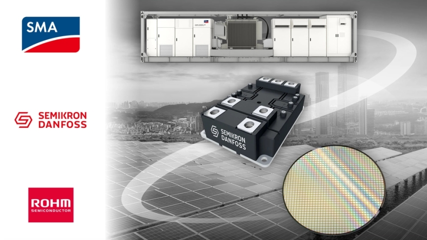
  SMA Solar Technology AG, a leading global specialist in photovoltaic and storage system technology, adopts Semikron Danfoss’ Module with ROHM’s latest 2kV SiC MOSFETs inside its new large scale solar system “Sunny Central FLEX”, a modular platform designed to streamline and enhance grid connections for large-scale photovoltaic installations, battery storage systems, and emerging technologies.  “ROHM’s new 2kV class SiC MOSFETs are designed to enable simple and highly efficient converter topologies for 1500V DC-links. It is developed with high reliability targets and cosmic radiation robustness – addressing the stringent conditions and extended converter lifetime requirements of the photovoltaic sector and beyond,” says Wolfram Harnack, President at ROHM Semiconductor GmbH. “The technology of our SiC device structure and integrated on-chip gate resistance eases device paralleling and simplifies high power module designs. The mass production has started,” adds Harnack.  Semikron Danfoss’ SEMITRANS® 20 has designed for high power applications and fast-switching operations, it represents the next generation of power modules for large converters. SEMITRANS® 20 with ROHM’s 2kV SiC MOSFETs is an integral part of SMA’s Sunny Central FLEX. “Semikron Danfoss and ROHM have collaborated for over a decade, focusing primarily on the implementation of silicon carbide (SiC) in power modules. More recently, we have teamed up to integrate silicon IGBTs as well”, says Peter Sontheimer, Senior Vice President of Semikron Danfoss’ Industry division.  “The new SEMITRANS® 20 offers simple, efficient solutions for 1500VDC applications. These modules are ideal for solar and energy storage inverters. Upcoming high-power electric truck chargers, as well as wind converters, will also benefit,” adds Sontheimer.  "The cooperation between SMA, Semikron Danfoss and ROHM is proof of how the seamless integration of innovative technologies creates the conditions for future-oriented energy projects," said Bernd Gessner, Product Manager Power Conversion Systems at SMA. "The demands on these solutions are higher than ever. SMA has decades of expertise and fulfills the highest requirements in terms of performance, reliability, durability and flexibility. The fact that Sunny Central FLEX meets these highest future-proof standards is also the result of the excellent cooperation with our partners who share the same commitment to excellence."  About SMA Solar Technology AG        As a leading global specialist in photovoltaic and storage system technology, the SMA Group is setting the standards today for the decentralized and renewable energy supply of tomorrow. SMA’s portfolio contains a wide range of efficient PV and battery inverters, holistic system solutions for PV and battery-storage systems of all power classes, intelligent energy management systems and charging solutions for electric vehicles and power-to-gas applications. Digital energy services as well as extensive services round off SMA’s range. SMA inverters installed throughout the world within the last 20 years with a total output of approximately 144 GW help avoid the emission of more than 64 million tons of CO2. SMA’s multi-award-winning technology is protected by more than 1,600 patents and utility models. Since 2008, the Group’s parent company, SMA Solar Technology AG, has been listed on the Prime Standard of the Frankfurt Stock Exchange (S92) and is listed on the SDAX index.  About Semikron Danfoss        Semikron Danfoss is a global technology leader in power electronics. Our product offerings include semiconductor devices, power modules, stacks and systems. In a world that is going electric, Semikron Danfoss technologies are more relevant than ever. With our innovative solutions for automotive, industrial and renewable applications we help the world utilize energy more efficiently and sustainably and thus to significantly reduce overall CO2 emissions – facing one of the biggest challenges today. We take care of our employees and create value for our customers by investing significantly in innovation, technology, capacity and service to deliver best-in-industry performance and for a sustainable future. Semikron Danfoss is a family-owned business, merged by SEMIKRON and Danfoss Silicon Power in 2022. We employ more than 3,500 people in 28 locations across the world. Our global footprint with production sites in Germany, Brazil, China, France, India, Italy, Slovakia and the United States ensures an unmatched service for our customers and partners. We offer more than 90 years of combined expertise in power module packaging, innovation and customer applications – making us the ultimate partner in power electronics.
Key word:
Release time:2025-04-29 10:49 reading:348 Continue reading>>
Renesas Introduces Highly Integrated LCD Video Processor that Enables Next-Generation ASIL B Automotive Display <span style='color:red'>System</span>s
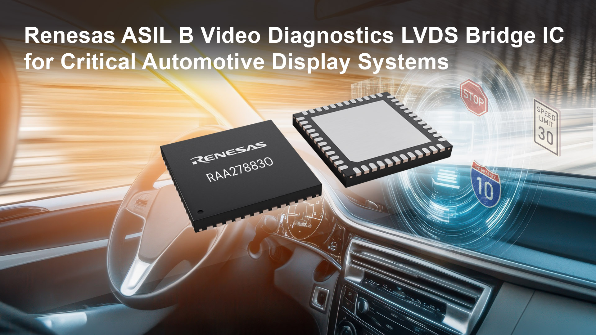
  Renesas Electronics Corporation (TSE:6723), a premier supplier of advanced semiconductor solutions, today introduced the RAA278830 Video Diagnostics Bridge IC, a highly integrated dual Low-Voltage Differential Signal (LVDS) LCD video processor. The new IC integrates many of the features necessary to design ISO 26262-compliant ASIL B automotive display systems such as heads-up-displays (HUD), digital instrument clusters, camera monitor systems (CMS), and electronic mirrors.  As automotive safety systems are increasingly dependent on display systems, it has become more critical that clear, uncorrupted images be presented to the driver. Missing frames, frozen images, and even incorrect warning icons can seriously compromise driver safety. The RAA278830 addresses these concerns with Functional Safety features built into the device specifically to avoid any corruption of images through monitoring of the signal integrity as well as the video content itself. The internal diagnostics and measurement engines can detect frozen video, incorrect colors, broken or corrupt video images, as well as flashing, flickering, and video images that could obstruct the driver’s view of the road (in the case of HUD systems).  Renesas’ Automotive Video Signal Processing Expertise  Renesas has a long and successful track record of providing video signal processing solutions for the automotive market. In addition to standard analog video decoders, Renesas offers the award-winning Automotive HD-Link (AHL) family of products that enables high-resolution images to be transported over low-cost cables and connectors. The RAA278830 adds to Renesas’ leading line of integrated LCD controllers that have been implemented worldwide.  Key Features of the RAA278830  Dual Open-LDI Input/Output  ISO 26262 Functional Safety ASIL B rating  CRCs, parity, BIST, and redundancy safety mechanisms implemented throughout the entire data path  Video Diagnostic Capabilities  Input/Output monitoring of video timing, signal integrity, and content  Flickering, flashing, occlusion, and glare detection  Spread Spectrum for lower system level EMI profile  Image enhancement engine for superior image quality  Dual host interface: I2C & SPI (configurable)  SPI-Flash based OSD as well as an embedded font based OSD  SPI boot capability (boot from SPI Flash, no MCU needed)  Supports multi-bank for fail-safe OTA updates  Space-efficient 72SCQFN, 10mm x 10mm  AEC-Q100 Grade 2 qualified  “Our automotive customers have consistently asked us to add functional safety features to our industry-leading video processing technology,” said Jason Kim, Vice President and General Manager of the Configurable Mixed-Signal Division at Renesas. “The RAA278830 delivers all of the features needed to create safe, easy-to-implement and economical LCD display for all types of passenger vehicles.”
Key word:
Release time:2025-04-01 14:36 reading:461 Continue reading>>
ROHM’s New TVS Diodes: Supporting High-Speed CAN FD In-Vehicle Communication <span style='color:red'>System</span>s for Autonomous Driving
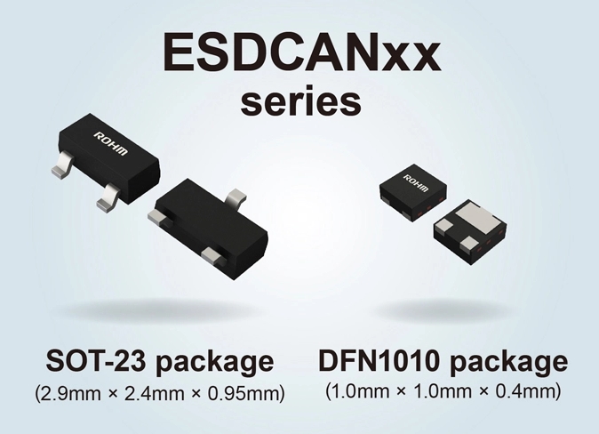
  ROHM has developed bidirectional TVS (ESD protection) diodes compatible with CAN FD (CAN with Flexible Data rate) high-speed in-vehicle communication. Such protocols are seeing an increased demand in line with the ongoing advancement in autonomous driving and advanced driver assistance systems (ADAS). CAN FD is a crucial communication technology for safe, real-time data transmission between ECUs (Electronic Control Units) in vehicles. The new products achieve high-quality in-vehicle transmission by protecting electronic devices such as ECUs from surges and electrostatic discharge (ESD) while maintaining signal integrity in high-speed communication systems such as CAN FD.  The rapid evolution of autonomous driving technology and ADAS is boosting the demand for faster, more reliable automotive communication. Autonomous driving in particular requires quick and accurate processing of vast amounts of data from sensors such as cameras, LiDAR and radar - leading to the adoption of CAN FD that enables faster, higher capacity data transfer compared to traditional CAN used in automotive communication.  At the same time, to achieve high-speed in-vehicle communication, it is necessary to ensure stable transmission even under harsh environments. This has led to a growing demand for protection components that offer low terminal capacitance along with superior surge current rating and clamping voltage performance. As a result, the market for TVS diodes for automotive communication is expected to continue to grow in the future.  To meet market needs, ROHM developed the ESDCANxx series that combines low terminal capacitance with excellent surge tolerance. Two package types are available: SOT-23 (2.9mm × 2.4mm) and DFN1010 (1.0mm × 1.0mm), both supporting standoff voltages (VRWM) of 24V and 27V. The SOT-23 package includes four models: 24V ESDCAN24HPY / ESDCAN24HXY and 27V ESDCAN27HPY / ESDCAN27HXY. Similarly, the DFN1010 package is also offered in four models: 24V ESDCAN24YPA / ESDCAN24YXA and 27V ESDCAN27YPA / ESDCAN27YXA, totaling 8 products in the lineup.  The new products feature an optimized element structure that reduces terminal capacitance to a maximum of 3.5pF, preventing signal degradation during high-speed communication. High surge tolerance is also achieved, significantly improving the protection of electronic devices in automotive environments. For example, the 27V products of the DFN1010 package delivers approx. 3.2 times higher surge current rating and 16% lower clamping voltage compared to standard CAN FD-compatible products. This effectively safeguards expensive surge-sensitive electronic devices such as in-vehicle ECUs, ensuring high reliability even under harsh automotive environments. Going forward, ROHM will continue to develop products that support even faster in-vehicle communication in autonomous driving and communication environments - contributing to realizing a safer, more advanced mobility society.  Application Examples        • Autonomous driving and Advanced Driver Assistance Systems (ADAS)  • Automotive electric powertrain systems  • In-vehicle infotainment systems  Online Distributor Information        Sales Launch Date: December 2024  Pricing: $0.9/unit (excluding tax)  Target Products  SOT23 Package: ESDCAN24HPY, ESDCAN24HXY, ESDCAN27HPY, ESDCAN27HXY  DFN1010 Package: ESDCAN24YPA, ESDCAN24YXA, ESDCAN27YPA, ESDCAN27YXA  Terminology         CAN FD (CAN with Flexible Data Rate)  An extension of the CAN (Controller Area Network) standard, CAN FD offers faster data transfer speeds compared to conventional CAN, enabling the exchange of large volumes of data. Real-time communication between multiple in-vehicle electronic units (ECUs) is essential in systems like autonomous driving and ADAS.  TVS Diode (Transient Voltage Suppression Diode)  A semiconductor device designed to protect circuits from overvoltage, surges, and electrostatic discharge (ESD). TVS diodes absorb sudden voltage and current spikes (surges) to prevent circuit damage and malfunction. In automotive environments, safeguarding against severe electrical fluctuations is crucial.  Terminal Capacitance  Unwanted capacitance components that arise in electronic parts. When terminal capacitance is high, signal degradation occurs during high-speed transmission, making it important to reduce terminal capacitance for in-vehicle communication  Surge Current Rating  The maximum surge current a TVS diode can withstand. The higher the surge current rating, the stronger the protection against severe electrical fluctuations in automotive environments.  Clamping Voltage  The voltage maintained in the circuit when the TVS diode suppresses overvoltage caused by surges or other transient events. A lower clamping voltage provides more effective protection for circuits and devices, increasing the reliability of automotive equipment.
Key word:
Release time:2025-03-11 09:29 reading:365 Continue reading>>
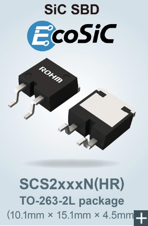
ROHM’s New SiC Schottky Barrier Diodes for High Voltage xEV <span style='color:red'>System</span>s: Featuring a Unique Package Design for Improved Insulation Resistance
  ROHM has developed surface mount SiC Schottky barrier diodes (SBDs) that improve insulation resistance by increasing the creepage distance between terminals. The initial lineup includes eight models - SCS2xxxNHR - for automotive applications such as onboard chargers (OBCs), with plans to deploy eight models - SCS2xxxN - for industrial equipment such as FA devices and PV inverters in December 2024.  The rapidly expanding xEV market is driving the demand for power semiconductors, among them SiC SBDs, that provide low heat generation along with high-speed switching and high-voltage capabilities in applications such as onboard chargers. Additionally, manufacturers increasingly rely on compact surface mount devices (SMDs) compatible with automated assembly equipment to boost manufacturing efficiency. Compact SMDs tend to typically feature smaller creepage distances, fact that makes high-voltage tracking prevention a critical design challenge.  As leading SiC supplier, ROHM has been working to develop high-performance SiC SBDs that offer breakdown voltages suitable for high-voltage applications with ease of mounting. Adopting an optimized package shape, it achieves a minimum creepage distance of 5.1mm, improving insulation performance when contrasted with standard products.  The new products utilize an original design that removes the center pin previously located at the bottom of the package, extending the creepage distance to a minimum of 5.1mm, approx. 1.3 times greater than standard products. This minimizes the possibility of tracking (creepage discharge) between terminals, eliminating the need for insulation treatment through resin potting when surface mounting the device on circuit boards in high voltage applications. Additionally, the devices can be mounted on the same land pattern as standard and conventional TO-263 package products, allowing an easy replacement on existing circuit boards.  Two voltage ratings are offered, 650V and 1200V, supporting 400V systems commonly used in xEVs as well as higher voltage systems expected to gain wider adoption in the future. The automotive-grade SCS2xxxNHR are AEC-Q101 qualified, ensuring they meet the high reliability standards this application sector demands.  Going forward, ROHM will continue to develop high-voltage SBDs using SiC, contributing to low energy consumption and high efficiency requirements in automotive and industrial equipment by providing optimal power devices that meet market needs.  Application Examples◇ Automotive applications: Onboard chargers (OBCs), DC-DC converters, etc.  ◇ Industrial Equipment: AC servo motors for industrial robots, PV inverters, power conditioners, uninterruptible power supplies (UPS), and more  Online Sales InformationAvailability: The SCS2xxxxNHR for automotive applications are available now.  The SCS2xxxN for industrial equipment are scheduled in December 2024.  Pricing: $10.50/unit (samples, excluding tax)  Online Distributors: DigiKey™, Mouser™ and Farnell™  The products will be offered at other online distributors as they become available.  EcoSiC™ BrandEcoSiC™ is a brand of devices that leverage silicon carbide, which is attracting attention in the power device field for performance that surpasses silicon. ROHM independently develops technologies essential for the advancement of SiC, from wafer fabrication and production processes to packaging, and quality control methods. At the same time, we have established an integrated production system throughout the manufacturing process, solidifying our position as a leading SiC supplier.  TerminologyCreepage Distance  The shortest distance between two conductive elements (terminals) along the surface of the device package. In semiconductor design, insulation measures with such creepage and clearance distances must be taken to prevent electric shocks, leakage currents, and short-circuits in semiconductor products.  Tracking (Creepage Discharge)  A phenomenon where discharge occurs along the surface of the package (insulator) when high voltage is applied to the conductive terminals. This can create an unintended conductive path between patterns, potentially leading to dielectric breakdown of the device. Package miniaturization increases the risk of tracking by reducing creepage distance.  Resin Potting  The process of encapsulating the device body and the electrode connections between the device and circuit with resin, such as epoxy, to provide electrical insulation. This provides durability and weather resistance by protecting against water, dust, and other environmental conditions.  AEC-Q101 Automotive Reliability Standard  AEC stands for Automotive Electronics Council, a reliability standard for automotive electronic components established by major automotive manufacturers and US electronic component makers. Q101 is a standard that specifically applies to discrete semiconductor products (i.e. transistors, diodes).
Key word:
Release time:2024-11-20 14:00 reading:504 Continue reading>>
Nidec’s Motor for Battery-assisted Bicycles is Adopted for Use in Taiyo Yuden’s Regenerative <span style='color:red'>System</span> that Keeps Them Running for 1,000km per Charge
  Nidec Corporation (TSE: 6594; OTC US: NJDCY) (“Nidec” or the “Company”) today announced that a motor that it developed for regenerative system-based battery-assisted bicycles has been adopted for use in FEREMO™, the regenerative power assistance system*1 that Taiyo Yuden Co., Ltd. (“Taiyo Yuden”) produced keeps a bicycle running for up to 1,000km on a single charge*2  FEREMO™, the regenerative power-assisted system that Taiyo Yuden developed, uses its power-assisting motor as a generator when the person on a bicycle puts on the brake or has his/her feet off the pedals, to collect and reuse motion energy.  This feature enables FEREMO™ to enjoy a significantly longer per-charge running distance, or up to 1,000km, than conventional power-assisting systems. In addition, with speed suppressed while the regenerative system is on, one can ride a bicycle safely even on a downhill.  Nidec’s power-assisted bicycle motor installed in FEREMO™ was designed exclusively for the system. While conventional power-assisting systems merely engage in powered operation (i.e., driving a motor with battery-generated electricity), this new motor operates as a generator when a bicycle decelerates, engaging in regeneration (i.e., rotating a motor with external power to generate electricity). In comparison with the Company’s other existing motors, this latest model boasts 30% more regenerative electric power, which is an industry-leading power generation efficiency, to help FEREMO™ achieve the 1,000km travelling distance. Furthermore, unlike assistance-only motors, load is constantly on the motor, making it more durable, low-noise, and radiation-efficient than conventional models.  As the world’s leading comprehensive motor manufacturer, Nidec stays committed to developing products with its technologies to make light, thin, short, and small products, as well as productivity enhancement and control technologies; and to proposing, at an overwhelming speed, revolutionary solutions that contribute to the lives of people around the world.  *1: FEREMO™  are Taiyo Yuden Co., Ltd.’s registered trademark or trademark for use in Japan  *2. According to Taiyo Yuden’s prototype vehicle measurement patterns (eco mode: 1,000km; middle mode: 200km; and high mode: 100km) based on the Japanese Industrial Standards
Key word:
Release time:2024-04-23 11:47 reading:1381 Continue reading>>
3PEAK Partners with IAR to Build a New Embedded Development Ecosystem!
  On January 18, 2024, 3PEAK and IAR jointly announced that IAR's flagship product, IAR Embedded Workbench for Arm, fully supports 3PEAK's mainstream TPS32 mixed-signal microcontrollers, giving developers a more complete and efficient development solution.  Based in China, 3PEAK provides analog chips alongside embedded processors and solutions and has sales and technical support networks across the USA, Europe, Japan, South Korea, and Taiwan (China). After years of deep exploration in the signal chain and power management domains, 3PEAK ventured into the embedded processor sector and achieved notable success.  Following two years of dedicated research and development, and through careful process selection and strict quality control efforts, 3PEAK successfully launched its first mixed-signal MCU platform. The TPS32 Series is the flagship brand of 3PEAK's independently developed mixed-signal microcontrollers. Through our deep understanding of vertical applications and continuous exploration of customer needs, 3PEAK introduced the TPS325M0 Series and TPS325M5 Series to serve a broad range of industrial applications, which have rapidly earned widespread adoption and praise from leading industry customers.  The IAR Embedded Workbench remains the optimal solution for many embedded software developers worldwide. This powerful toolkit provides comprehensive and efficient support for millions of developers. It enables developers to fully utilize code optimization features and offers a range of powerful debugging functions, including code and data breakpoints, runtime stack analysis, and call stack visualization. Additionally, the IAR Embedded Workbench features C-STAT, a static code analysis tool, and C-RUN, a dynamic code analysis tool, to help developers identify potential issues early and improve code quality. Notably, IAR also offers a TÜV SÜD-certified functional safety version that meets functional safety certification standards like ISO 26262. This version is an important tool for developers of functional safety products.  Ms. Chen Lihua, Senior Director of the 3PEAK MCU BU, said,  "While we are focused on providing high-quality devices, 3PEAK is also committed to creating an easy-to-use, high-quality, comprehensive, and open hardware and software development ecosystem for users. We are honored to be able to establish a partnership with renowned toolchain provider IAR. Our relationship has just started, but we expect to make steady progress. IAR's comprehensive support for 3PEAK devices and 3PEAK's full TPS32 SDK software package based on the IAR Embedded Workbench for Arm are just the first results of our work together. We believe that soon we will expand our collaboration with IAR into more areas to build a new embedded development ecosystem and create genuine value and convenience for our customers.  Kiyo Uemura, Vice President of IAR Asia-Pacific Region, expressed,  We are delighted to partner with 3PEAK, and we look to the future with confidence and anticipation. We have long recognized China's key position in the global market, with its vast potential and endless opportunities. As both a listed and domestically influential semiconductor company, 3PEAK possesses powerful technical capabilities and persistently pursues innovation. Our collaboration with 3PEAK highlights our mutual trust. Both companies will leverage their technical strengths in their respective fields to build a vibrant embedded ecosystem, as well as provide developers with world-class development tools and original manufacturer technical support.
Key word:
Release time:2024-03-22 14:51 reading:1964 Continue reading>>
NOVOSENSE's isolated driver with protection function helps enhance the safety and stability of the electronic control system in the new energy vehicle
  The main drive electronic control system is an important part of a new energy vehicle. This article will start from the system block diagram of the electronic control system, introduce the components of the system and their functions, and focus on the use of NOVOSENSE's single-channel isolated driver with protection function NSI6611, in the electronic control system: its Miller clamp function can well prevent short circuits; and the DESAT function can shut down IGBT / SiC in time when a short circuit occurs, protecting IGBT / SiC from damage and ensuring safe and stable operation of the system.  Contents  1)Introduction to the main drive electronic control system driver and the NSI6611-based driver board  1. Composition of the main drive electronic control system  2. Main chips on the driver board  3. Interface definition  4. NSI6611 application circuit  2)Introduction to Miller clamp and the active Miller clamp function of NSI6611  1. Miller effect  2. Active Miller clamp  3. Short circuit detection of power devices  3)Introduction to the DESAT protection function of NSI6611  1. DESAT detection peripheral circuit configuration and parameters  2. DESAT protection timing  3. Soft turn-off function  1) Introduction to the main drive electronic control system driver and the NSI6611-based driver board  1.1 Composition of the main drive electronic control system  The main drive electric control system consists of low voltage battery, VCU, MCU, high voltage battery and resolver three-phase motor. As shown in Figure 1 below, inside the blue dotted line is the main drive motor controller part and inside the red dotted line is the driver board that will be highlighted in this article.  Functionally, the low voltage battery provides low voltage power supply for the system, and the VCU sends instructions to the electronic control system via the CAN bus and reads the status of the electronic control system; the high voltage battery provides high voltage power supply, and the Flyback circuit provides positive and negative voltages for the IGBT driver to drive the three-phase motor; the LDO (low dropout linear regulator) provides +5V power supply for the driver chip. NOVOSENSE's high voltage isolated driver NSI6611 is used to drive the IGBT and SiC modules; the current sampling circuit and resolver-to-digital converter are used to control motor operation.  In the main drive electronic control system, NOVOSENSE provides a variety of chips, including the CAN interface chip, resolver-to-digital converter, power supply chip and high voltage isolated driver chip.  1.2 Main chips on the driver board  Figure 2 below is a three-phase drive circuit board designed based on NOVOSENSE's single-channel smart isolated driver NSI6611. The six chips in the blue boxes are all NSI6611. The driver board also uses NOVOSENSE's Flyback power control chip NSR22401 to provide positive and negative voltages for the high voltage drive side of NSI6611; the LDO chip NSR3x provides 5V power supply for the low voltage side of NSI6611.  NSI6611 is an automotive-grade, high voltage isolated gate driver with protection function that can drive IGBTs and SiCs, and it supports a peak voltage of up to 2121V and a maximum drive current of 10A without the need for an external drive circuit; CMTI (common-mode transient immunity) can be as high as 150kV/μs. In addition, it integrates active Miller clamp and DESAT (desaturation) protection, soft turn-off and ASC (active short circuit) functions internally, with an operating temperature range of -40°C to +125°C.  1.3 Interface definition  As shown in Figure 3 below, the left side of the driver board is the signal interface between the driver board and the control board, including 6 input signals provided by the control board for PWM control; 6 FAULT output signals provided to the control board when NSI6611 detects IGBT overcurrent or undervoltage; 6 Ready output signals used to indicate whether the NSI6611 power supply is undervoltage; and 2 RESET input signals that control 3 high sides and 3 low sides respectively. The right side of the driver board is the power interface, and the power supply voltage range is 9V to 16V.  1.4 NSI6611 Application Circuit  Figure 4 below is the drive circuit of NSI6611. The left side is the low voltage control side. The 100Ω resistor connected in series on the signal line can effectively reduce signal reflection; since the Fault and Ready signals have an internal Open Drain structure, a 5.1kΩ pull-up resistor needs to be added. In addition, the RC circuit composed of the PWM signal and a 1nF capacitor can filter out high-frequency signals, and a 0.1μF decoupling capacitor is added to VCC1.  The right side is the high voltage drive side. Two 1206 package gate resistors are connected in parallel. The gate has a 10k pull-down resistor. The gate capacitance can be adjusted for different applications. The CLAMP pin is connected to the GATE through a 0Ω resistor.  2) Introduction to Miller clamp and the active Miller clamp function of NSI6611  2.1 Miller effect  The Miller effect refers to the phenomenon in a transistor or field effect tube that the capacitance at the output of the amplifier increases due to the interaction between the input capacitance and the gain of the amplifier. It can not only increase switching delay, but also cause parasitic turn-on.  Due to the inherent characteristics of semiconductors, there are various parasitic capacitances inside the IGBT. The capacitance between the gate and collector is called Miller capacitance. It is often seen in tests that the gate voltage does not rise directly to the VCC voltage, but rises to a voltage plateau, maintains for a period of time and then rises again. This voltage plateau is the Miller plateau, which is generated by Miller capacitance.  Miller capacitance may also cause false turn-on of the low side. Typically, motor drives require the use of the high and low sides. When Q2 is turned off and Q1 is turned on, a certain current will be generated due to the high dv/dt and Miller capacitance. We can calculate the current by using the formula I=C * dv/dt. The current flowing through the gate resistor will generate a VGE voltage. When this voltage exceeds the turn-on threshold of Q2, Q2 will turn on, and at this time, Q1 is already in the ON state, thus causing a shoot-through short circuit.  2.2 Active Miller clamp  In order to solve the problem of shoot-through caused by the Miller effect, negative voltage turn-off can be used, but this will increase the complexity of the power supply design and increase the BOM cost; the second option is to use a driver chip with Miller clamp function to control the IGBT turn-off process.  The IGBT turn-off process controlled by a driver chip with Miller clamp function is shown in Figure 6 below. First, the OUTL pin is turned on, causing the gate voltage to drop; when the gate voltage drops below the CLAMP threshold, the CALMP pin is turned on, causing the OULT pin to turn off. The resulting path can effectively bypass the gate resistor, thus avoiding the phenomenon of shoot-through. It is worth noting that the Miller clamp module only works when the IGBT is turned off.  2.3 Short circuit detection of power devices  IGBT and SiC devices vary in their short circuit capabilities. Before using a power device to design a drive system, you must first understand its basic parameters such as maximum voltage, maximum current and Rdson (on-resistance). Short-circuit capability is also a parameter worthy of focus, since the short circuit characteristics of the device need to be known when short circuit protection is designed.  Take the short circuit characteristic parameters of the IGBT as an example. At 25°C, its maximum short circuit time is 6μs, which means that the IGBT needs to be turned off in time within 6μs. When the short circuit current reaches 4800A, the value is already several times the normal operating current. Once a short circuit occurs, a large amount of heat will be generated instantly, causing the junction temperature to rise sharply. If it is not turned off in time, the device will be burned and there is even a risk of fire. This must be avoided in system design.  Generally, the short circuit time of IGBT can reach up to 10μs, while the short circuit time of SiC is only 2~3μs, which brings great challenges to short circuit protection. Therefore, short circuit must be detected and turn-off must be performed in time.  Method 1 is current detection. A resistor is connected in series with the IGBT, or a current sensor is used to directly detect the overcurrent condition. However, this will increase the cost significantly and make the circuit system more complex.  Method 2 is desaturation detection, also known as DESAT protection. As shown in Figure 7 below, we can see from the graph of VCE voltage and collector current that when VCE is less than 0.4V, no current flows through the cut-off region; as the VCE voltage increases, the current also increases and a saturation region appears, and then it enters the linear region, i.e., the desaturation region.  Usually, when the IGBT works in the saturation region, it will enter the desaturation region once a short circuit occurs. It can be seen that the VCE voltage generally does not exceed 2V in the saturation region; if it enters the desaturation region, VCE will rise rapidly and even reach the system voltage. Desaturation detection is to detect whether the IGBT has entered the desaturation region by detecting the VCE voltage.  3) Introduction to the DESAT protection function of NSI6611  3.1 DESAT detection peripheral circuit configuration and parameters  DESAT detection consists of NSI6611 and external DESAT capacitor, resistor and high voltage diode. The NSI6611 chip integrates a 500μA constant current source and comparator internally.  When the IGBT is turned on normally, the VCE voltage is very low, basically below 2V, and the diode is in a forward turn-on state. The voltage value of VDESAT is equal to the voltage drop of the resistor plus the voltage drop of the diode, plus the VCE voltage. Assuming that the resistance of the resistor is 100Ω, the forward voltage drop of the diode is 1.3V, and VCE is 2V, then, according to the formula in Figure 8, we can get: When the IGBT is turned on normally, the voltage detected by DESAT is basically less than 3.35V.  When the IGBT is short-circuited, the VCE voltage will rise rapidly. At this time, the diode is in the OFF state, and the current will flow to the DESAT capacitor and charge it. Since the DESAT current of NSI6611 is 500μA and the DESAT threshold is 9V, this means that a capacitor needs to be matched to charge the DESAT capacitor to 9V at 500μA within the short circuit time.  Assuming that the DESAT capacitance is 56pF, according to the capacitor charging formula in Figure 8: the charging time of the capacitor is about 1μs; plus the blanking time of 200ns and the filtering time of 200ns, the total short circuit protection response time is 1.4μs. This time is not only shorter than the safe short circuit time of IGBT, but also shorter than the safe short circuit time of SiC.  3.2 DESAT protection timing  Figure 9 below is the DESAT protection timing diagram. It can be seen from the figure that in step 1, GATE rises and DESAT starts the blanking time; in step 2, the blanking time ends and the DESAT current is turned on, and if the IGBT is short-circuited, the diode enters the cut-off state and the DESAT current charges the capacitor; in step 3, when the DESAT capacitor is charged to the threshold of 9V, the filtering time of DESAT protection starts; in step 4, the filtering time ends and GATE is turned off.  Figure 9: DESAT protection timing diagram  3.3 Soft turn-off function  As mentioned above, GATE is turned off when a DESAT fault is detected. So, is it enough to just turn it off normally? Not really. When a short circuit occurs, the IGBT current is at least 6 to 8 times the normal current. According to the formula, the voltage is equal to the stray inductance of the system multiplied by di/dt (V=Ls*di/dt). If such a large current is turned off quickly, a large VCE voltage will inevitably be generated, which is enough to damage the IGBT. There are only two ways to reduce VCE overshoot: one is to reduce stray inductance, and the other is to reduce di/dt.  Firstly, due to the parasitic parameters of the device, PCB routing, structural design, etc., there is inevitably a certain amount of stray inductance; secondly, to reduce di/dt, under the premise of a certain current, the only way is to increase the turn-off time, that is, let the IGBT turn off slowly for safe turn-off. NSI6611 can provide 400mA soft turn-off, thereby suppressing VCE overshoot and effectively solving the problem of device protection.
Key word:
Release time:2024-02-29 14:26 reading:3486 Continue reading>>
NOVOSENSE Launches NSI22C1x Series Isolated Comparators to Help Create More Reliable Industrial Motor Drive <span style='color:red'>System</span>s
  NOVOSENSE announced the launch of its NSI22C1x series isolated comparators based on capacitive isolation technology, which include NSI22C11 isolated single-ended comparators for overvoltage and overtemperature protection and NSI22C12 isolated window comparator for overcurrent protection. The NSI22C1x series can be used for overvoltage, overtemperature and overcurrent protection of industrial motor drives, solar inverters, uninterruptible power supplies and on-board chargers. While improving system reliability, it supports higher power density system designs and simplifies peripheral circuits to reduce the size of system protection circuits by 60% compared to the traditional discrete scheme.  Industrial motor drive systems, for example, are developing towards higher efficiency, higher power density and higher reliability. At the same time, with the application of wide bandgap semiconductors represented by SiC and GaN in power devices, higher requirements are placed on system reliability, especially the response time of overcurrent and short-circuit protection. The NSI22C1x series isolated comparators launched by NOVOSENSE can meet the growing demand for high reliability, high efficiency and compact design in industrial motor systems.  Ultra-low propagation delay and ultra-high CMTI support higher power density designs  The application environment of industrial motor drive systems is complex and harsh. Unexpected conditions such as bridge arm shoot-through, phase-to-phase short-circuit and ground short-circuit may occur, resulting in excessive current flowing into the motor drive system and causing damage to the driver. Traditional overcurrent detection design uses a discrete scheme of general-purpose comparators and optocouplers, with a response time of 3~5µs. As power devices shift from silicon-based IGBTs to third-generation semiconductors SiC and GaN, their short-circuit withstand time has been shortened to less than 1µs, which can no longer be met by the traditional scheme.  VIN(CH1), VOUT(CH2), VREF=320mV (protection threshold), NSI22C12 propagation delay measured 144ns  Meanwhile, general-purpose op amps/comparators have limited common-mode voltage tolerance and are limited in applications such as DC+ overcurrent and phase current overcurrent detection. If only DC- overcurrent is monitored, the fault condition of the motor shell being shorted to ground cannot be covered. NOVOSENSE's NSI22C12 isolated comparators provide a single-chip isolated overcurrent protection scheme that can cover a more comprehensive range of fault scenarios, support a maximum propagation delay of 250ns and bi-directional overcurrent protection, and provide CMTI (Common-Mode Transient Immunity) of up to 150kV/μs, which greatly improves system reliability and supports the adoption of higher power density designs for customers' motor drive systems.  VIN=0V, VOUT(CH1), CMTI(CH3)=150kV/μs, VOHmin =2.40V>0.7*VDD2(VDD2=3.3V)  When the primary and secondary sides of NSI22C12 withstand a CMTI of up to 150kV/μs, the output still maintains a high level and overcurrent protection will not be mistakenly triggered.  Simplified system designs reduce the size of system protection circuits by 60%  In industrial motor drive systems, the bill of materials for the overcurrent protection scheme based on general-purpose comparators and optocouplers is up to 27 pieces, and the system failure rate of peripheral circuits consisting of numerous discrete devices is relatively higher. NSI22C12 integrates a high-voltage LDO with a primary-side supply range of 3.1~27V, which can help customers reduce extra step-down regulators; NSI22C12 also integrates a 100μA ±1.5% high-precision current source, which can help customers achieve ±20mV~±320mV bidirectional threshold adjustment with only a single resistor on board.  With the support of a highly integrated design, the overcurrent protection scheme using NSI22C12 isolated comparators can reduce the bill of materials to 11 pieces and reduce the size of system protection circuits by 60%, greatly reducing the use of discrete devices, simplifying the system design, and further improving system reliability. At the same time, in some systems with fast protection requirements, using NSI22C12 isolated comparators can reduce the use of high-speed optocouplers and provide customers with more cost-effective design options.  Typical application block diagram of NSI22C12 for bus/phase current protection in motor drive systems  Packaging and selection  NSI22C11 isolated single-ended comparator and NSI22C12 isolated window comparator NSI22C12 are available in both SOP8 package (for basic isolation) and SOW8 package (for reinforced isolation). In addition, the NSI22C1x series supports a wide operating temperature range of -40°C to 125°C. Currently, the industrial version of the NSI22C1x series has been put into mass production, and the AEC-Q100 automotive version is expected to be launched in the second half of 2024.
Key word:
Release time:2024-02-28 13:58 reading:3044 Continue reading>>
Nidec Power Train <span style='color:red'>System</span>s Develops Industry-first Solenoid Valve for Blow-by Gas Leak Diagnosis
  Nidec Power Train Systems Corporation (“Nidec Power Train Systems” or the “Company”), a wholly owned subsidiary of Nidec Corporation, announced today that it has developed a solenoid valve for automotive engines’ blow-by gas leak diagnosis.  Nidec Power Train Systems’ Latest Solenoid Valve for Blow-by Gas Leak Diagnosis  In any internal-combustion engine, there is a tiny gap between its piston and the cylinder containing it, from which high-pressure exhaust steam from the combustion stroke and unburned mixture leak into the crankcase. Such gas, called blow-by gas, causes air pollution. This is why recent cars are required to have a closed crankcase to keep such gases, and use a reducing device to return internally accumulating gas to the inlet pipe, thereby to mix the gas with newly inspired air, and send the mixture into the combustion chamber again.  In North America, meeting the requirements of the On-Board Diagnostics II (OBDII) of the California Air Resources Board (CARB), the world’s strictest rules of their kind, requires a car to have a blow-by gas leak diagnosis function installed, and the above product is the industry’s first model to satisfy those needs.  This product, which is connected to a breather hose that reduces blow-by gas, is used to block a gas passage during a leak diagnosis. Thus, measuring the pressure inside the engine, including the breather hose, enables a diagnosis to see if blow-by gas is leaking to the outside.  The inside of the blow-by gas passage of this and other products requires high reliability, as it is subject to harsh environments caused by, for example, the retention of unburned gas, engine oil, etc., and low temperatures. In that regard, Nidec Power Train Systems, a long-time developer and manufacturer of transmissions and engine solenoid valves, successfully utilized its knowhow to develop this new product.  As a member of the world’s leading comprehensive motor manufacturer, Nidec Power Train Systemsstays committed to developing products based on its technologies to create light, thin, short, small, high-efficiency, and highly controlled products, and proposing, at an overwhelming speed, groundbreaking solutions that contribute to the evolution of automobiles.
Key word:
Release time:2024-02-01 15:33 reading:2054 Continue reading>>

Turn to

/ 5

  • Week of hot material
  • Material in short supply seckilling
model brand Quote
RB751G-40T2R ROHM Semiconductor
TL431ACLPR Texas Instruments
MC33074DR2G onsemi
BD71847AMWV-E2 ROHM Semiconductor
CDZVT2R20B ROHM Semiconductor
model brand To snap up
TPS63050YFFR Texas Instruments
STM32F429IGT6 STMicroelectronics
ESR03EZPJ151 ROHM Semiconductor
BU33JA2MNVX-CTL ROHM Semiconductor
BP3621 ROHM Semiconductor
IPZ40N04S5L4R8ATMA1 Infineon Technologies
Hot labels
ROHM
IC
Averlogic
Intel
Samsung
IoT
AI
Sensor
Chip
About us

Qr code of ameya360 official account

Identify TWO-DIMENSIONAL code, you can pay attention to

AMEYA360 mall (www.ameya360.com) was launched in 2011. Now there are more than 3,500 high-quality suppliers, including 6 million product model data, and more than 1 million component stocks for purchase. Products cover MCU+ memory + power chip +IGBT+MOS tube + op amp + RF Bluetooth + sensor + resistor capacitance inductor + connector and other fields. main business of platform covers spot sales of electronic components, BOM distribution and product supporting materials, providing one-stop purchasing and sales services for our customers.

Please enter the verification code in the image below:

verification code