Murata Commercializes Broadband-Compatible 1210 inch size, in-vehicle PoC Inductors, Reducing Component Size and Weight
Key word:
Release time:2025-04-08 14:17 reading:261 Continue reading>>
Mazda and ROHM Begin Joint Development of Automotive Components Using Next-Generation Semiconductors
  Mazda Motor Corporation (hereinafter “Mazda”) and ROHM Co., Ltd. (hereinafter “ROHM”) have commenced joint development of automotive components using gallium nitride (GaN) power semiconductors, which are expected to be the next-generation semiconductors.  (Left) Ichiro Hirose, Director, Senior Managing Executive Officer and CTO of MAZDA / (Right) Katsumi Azuma, Member of the Board and Senior Managing Executive Officer of ROHM  Since 2022, Mazda and ROHM have been advancing the joint development of inverters using silicon carbide (SiC) power semiconductors under a collaborative framework for the development and production of electric drive units. Now, they have also embarked on the development of automotive components using GaN power semiconductors, aiming to create innovative automotive components for next-generation electric vehicles.  GaN is attracting attention as a next-generation material for power semiconductors. Compared to conventional silicon (Si) power semiconductors, GaN can reduce power conversion losses and contribute to the miniaturization of components through high-frequency operation.  Both companies will collaborate to transform these strengths into a package that considers the entire vehicle, and into solutions that innovate in weight reduction and design. Mazda and ROHM aim to materialize the concept and unveil a demonstration model within FY2025, with practical implementation targeted for FY2027.  “As the shift towards electrification accelerates in pursuit of carbon neutrality, we are delighted to collaborate with ROHM, which aims to create a sustainable mobility society with its outstanding semiconductor technology and advanced system solution capabilities, in the development and production of automotive components for electric vehicles” said Ichiro Hirose, Director, Senior Managing Executive Officer and CTO of Mazda. “We are excited to work together to create a new value chain that directly connects semiconductor devices and cars. Through collaboration with partners who share our vision, Mazda will continue to deliver products filled with the 'joy of driving' that allows customers to truly enjoy driving, even in electric vehicles.”  “We are very pleased to collaborate with Mazda, which pursues the 'joy of driving,' in the development of automotive components for electric vehicles” said Katsumi Azuma, Member of the board and Senior Managing Executive Officer of ROHM. “ROHM's EcoGaN™, capable of high-frequency operation, and the control IC that maximizes its performance are key to miniaturization and energy-saving. To implement this in society, collaboration with a wide range of companies is essential, and we have established various partnerships for the development and mass production of GaN. By collaborating with Mazda, which aims to create 'cars that coexist sustainably with the earth and society,' we will understand the requirements for GaN from the perspective of application and final product development, contributing to the spread of GaN power semiconductors and the creation of a sustainable mobility society.”  EcoGaN™ is a trademark or registered trademark of ROHM Co., Ltd.
Key word:
Release time:2025-03-31 15:46 reading:255 Continue reading>>
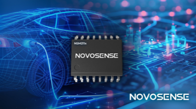
NSM211x Series High-Precision AEC-Q100 Current Sensors Eliminate Need for External Isolation Components
  NOVOSENSE Microelectronics, a semiconductor company specializing in high-performance analog and mixed-signal chips, has announced the NSM211x, a series of automotive-grade fully integrated high-bandwidth, high-isolation current sensors that both ensure precise current measurement and eliminate the need for any external isolation components.  On display at Electronica 2024 (Stand B5.450), the automotive-grade series targets applications including OBC/DC-DC converters, PTCs, automotive motor control, charging station current detection and fuel cell systems.  Certified to meet AEC-Q100 Grade 0 reliability standards, the series is designed to operate stably within a wide temperature range (-40 to 150°C) and addresses the needs of AC or DC current detection in automotive applications with a high isolation voltage, strong current handling capability and high reliability.  With a -3 dB bandwidth of up to 1 MHz and a response time of 400 ns, the NSM211x series helps control systems achieve rapid loop control and overcurrent protection. The series also features a creepage distance of up to 8.2mm and isolation voltage withstand of 5,000 Vrms per UL standards, with a maximum working isolation voltage of 1,618 Vpk.  It is available in three packaging options, SOP8, SOW16 and SOW10. These respectively have a primary side impedance of 1.2 mΩ, 0.85 mΩ/1 mΩ and an industry leading 0.27mΩ, with a continuous current handling capability of up to 100 A. Multiple product models are available for each package.  The current sensors integrate internal temperature compensation algorithms and offline calibration to enable a high measurement accuracy (<±2% sensitivity error and <±10 mV offset error) across the full temperature range, with no need for secondary programming.  The NSM211x series supports 3.3 V and 5 V power supply voltage as well as DC or AC current measurement with a current range of 5~200 A with options for reference voltage output, overcurrent protection output, and configurable overcurrent protection thresholds.
Key word:
Release time:2024-11-15 14:30 reading:515 Continue reading>>
What is “<span style='color:red'>component</span> placement” in PCB?
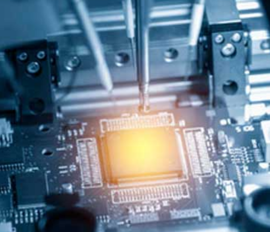
  Component placement is a critical step in the PCB assembly process where electronic components are precisely positioned and soldered onto the printed circuit board (PCB). This phase plays a crucial role in ensuring the functionality, reliability, and performance of the final electronic device. Let’s delve into the details of component placement in PCB assembly.  How many electronic components are there?1. Surface Mount Devices (SMDs):  – Passive Components: Resistors, capacitors, inductors.  – Active Components: Integrated circuits (ICs), transistors, diodes.  2. Through-Hole Components:  – Components with leads that pass through holes drilled in the PCB.  What is the component placement process?1. Design for Assembly (DFA)  Before physical assembly begins, the PCB layout and design must consider DFA principles:  – Component Orientation: Optimizing orientation for ease of assembly and efficient routing of traces.  – Clearance and Spacing: Ensuring adequate space for soldering and avoiding interference between components.  – Accessibility: Facilitating automated or manual assembly processes.  2. Automated Component Placement  Modern PCB assembly typically involves automated pick-and-place machines:  – Vision Systems: Cameras identify fiducial markers or component outlines on the PCB to align and place components accurately.  – Component Feeding: Components are loaded into feeders, which supply them to the pick-and-place machine.  – Pick-and-Place Process: The machine picks components from the feeder using vacuum nozzles, aligns them precisely over corresponding pads on the PCB, and places them gently using controlled motion.  3. Manual Component Placement  For specialized components or low-volume production, manual placement may be used:  – Skill and Precision: Technicians use hand tools like tweezers and magnifiers to place components accurately.  – Prototype Builds: Initial prototypes or small batches may benefit from manual placement for flexibility and customization.  What should be considered when placing components in PCB?Component placement is more than just arranging components on a board; it involves strategic decisions that impact the overall functionality and quality of the PCB. Proper placement not only ensures that the circuit operates correctly but also affects signal integrity, thermal management, and ease of assembly. Here are some crucial aspects to consider:  1. Design for Signal Integrity  Signal integrity is crucial for the proper operation of high-speed digital circuits and sensitive analog circuits. To maintain signal integrity:  – Minimize Trace Length: Place critical components closer together to minimize trace lengths, reducing signal delay and electromagnetic interference (EMI).  – Signal Paths: Follow a logical signal flow from input to output, avoiding crossing high-speed signals with noisy or high-current traces.  – Grounding: Ensure a solid ground plane and place components that require low impedance connections to ground strategically to minimize noise and ground loops.  2. Thermal Management  Certain components, such as power transistors or voltage regulators, generate heat during operation. Efficient thermal management is essential to prevent overheating and ensure reliability:  – Heat Sinks: Provide adequate space and mounting locations for heat sinks or thermal pads.  – Airflow: Arrange components to allow natural or forced airflow across heat-generating components.  – Isolation: Keep heat-sensitive components away from those generating significant heat to prevent thermal damage.  3. Manufacturability and Assembly  Designing for manufacturability involves ensuring that the PCB can be efficiently assembled with minimal errors and rework:  – Component Accessibility: Ensure components are placed such that they can be easily soldered by hand or by automated pick-and-place machines.  – Orientation: Align components consistently for ease of assembly and to avoid errors during soldering.  – Clearance and Spacing: Adhere to manufacturing guidelines for minimum clearance between components, ensuring soldering and inspection can be done without issues.  4. Electromagnetic Compatibility (EMC)  PCB layout plays a crucial role in achieving EMC compliance by reducing EMI emissions and susceptibility:  – Component Arrangement: Position sensitive components and traces to minimize loop areas and coupling.  – Shielding: Group and shield sensitive components from noise sources such as high-current paths or switching circuits.  – Grounding and Routing: Properly route and ground signal return paths to reduce loop areas and impedance discontinuities.  Best Practices for Component Placement– Start with Critical Components: Begin by placing critical components such as microcontrollers, connectors, and high-frequency components based on their functional and spatial requirements.  – Use Design Tools: Leverage PCB design software with simulation capabilities to visualize signal paths, analyze thermal performance, and optimize placement before fabrication.  – Iterative Refinement: Iterate the placement based on simulation results, design reviews, and practical considerations to achieve the best balance of performance and manufacturability.  – Documentation: Clearly label components with reference designators and polarity markings on the silkscreen layer. Maintain an updated BOM (Bill of Materials) to ensure accurate procurement and assembly.  ConclusionComponent placement in PCB assembly is a pivotal stage where careful planning, advanced technology, and skilled craftsmanship converge to create reliable electronic devices. By adhering to DFA principles, leveraging automation, and considering thermal and signal integrity factors, manufacturers can achieve efficient, high-quality assembly that meets the demands of today’s electronics industry. As technology advances, component placement continues to evolve, driving innovation and pushing the boundaries of what’s possible in electronic design and manufacturing.
Key word:
Release time:2024-07-18 11:48 reading:695 Continue reading>>
EMC Components : Guardians of Electronic Devices
  Electromagnetic interference (EMI) is a pervasive force in our modern world. It emanates from various sources such as radio waves, power lines, and even the devices we use daily. EMI can disrupt the operation of electronic devices, causing malfunctions, data corruption, or complete failure. This interference not only affects the device itself but can also radiate outward, potentially interfering with other nearby electronic systems.  Electromagnetic compatibility EMC components are crucial for addressing electromagnetic interference emissions and susceptibility issues. The correct selection and use of these components are prerequisites for electromagnetic compatibility design.  Therefore, we must have a deep understanding of these components in order to design electronic and electrical products that meet standard requirements and offer the best cost-effectiveness. Each electronic component has its own characteristics, so this article will discuss some common electronic components and circuit design techniques to reduce or suppress electromagnetic compatibility issues.  There are two basic groups of electronic components: leaded and lead-free components. Leaded components have parasitic effects, especially at high frequencies. The leads form a small inductance, approximately 1nH/mm/lead. The ends of the leads also produce a small capacitance effect, around 4pF. Therefore, the length of the leads should be kept as short as possible. Compared to leaded components, lead-free surface-mount components have smaller parasitic effects. Typical values are: 0.5nH parasitic inductance and around 0.3pF terminal capacitance.  EMC components are specialized electronic parts designed to mitigate the effects of electromagnetic interference. They act as shields, filters, and absorbers, safeguarding sensitive electronic circuits from unwanted electromagnetic disturbances. These components come in various forms, each serving a unique purpose in the quest for electromagnetic compatibility.  CapacitorsCapacitors are indispensable elements in EMC design, serving as robust tools for both filtering and bypassing unwanted noise and signals.  At their core, capacitors store and release electrical energy, but in the realm of EMC, they serve a dual purpose. Firstly, capacitors act as filters, blocking high-frequency noise and interference from entering sensitive circuits. By strategically placing capacitors in signal paths or power lines, designers can effectively attenuate EMI, preserving signal integrity and device performance.  Secondly, capacitors act as bypass components, providing a low-impedance path for high-frequency noise to dissipate harmlessly to ground. This prevents noise from propagating through the circuit and interfering with critical operations.  Ferrite Beads and ChokesFerrite beads and chokes are passive components commonly used to suppress high-frequency noise in electronic circuits. By introducing impedance to the flow of high-frequency signals, these components effectively filter out electromagnetic interference. They are often found in power lines, signal cables, and printed circuit boards, where they help maintain signal integrity and prevent interference from disrupting sensitive electronic components.  EMI FiltersEMI filters are active or passive devices that suppress conducted electromagnetic interference by attenuating noise on power lines and signal cables. These filters typically employ a combination of capacitors, inductors, and resistors to shunt high-frequency noise to ground, ensuring that only clean power reaches the electronic device. EMI filters are crucial in applications where strict electromagnetic compatibility standards must be met, such as medical devices, automotive electronics, and telecommunications equipment.  InductorsInductors, vital EMC components, establish a connection between magnetic and electric fields, offering sensitivity crucial for addressing electromagnetic interference (EMI). These components, akin to capacitors, tackle various EMC challenges effectively. There are two fundamental types: open-loop and closed-loop, distinguished by their magnetic field paths. Open-loop inductors, with magnetic fields traversing air, can induce radiation and EMI concerns. Axial winding is preferable over rod or coil designs to confine the magnetic field within the core.  Conversely, closed-loop inductors enclose the magnetic field entirely within a magnetic core, rendering them ideal for circuit design albeit pricier. Ferrite-core inductors are particularly suited for EMC applications due to their capacity to operate at high frequencies, ensuring efficient EMI suppression. In EMC endeavors, ferrite beads and clips emerge as specialized inductor types, catering to unique interference challenges.  Shielding MaterialsShielding materials, such as conductive foils, tapes, and coatings, create a barrier between sensitive electronic components and external electromagnetic fields. They prevent electromagnetic interference from penetrating or escaping from electronic enclosures, thereby minimizing the risk of interference-induced malfunctions. Shielding materials are widely used in consumer electronics, industrial machinery, and aerospace systems to ensure reliable operation in electromagnetic environments.  Surge SuppressorsSurge suppressors, also known as transient voltage suppressors (TVS), protect electronic circuits from voltage spikes and transient surges caused by lightning strikes, electrostatic discharge (ESD), or switching events. These components rapidly divert excess energy away from sensitive electronic components, preventing damage and ensuring the longevity of electronic devices. Surge suppressors find applications in power supplies, data communication systems, and automotive electronics, where robust protection against transient events is essential.  ConclusionThe role of EMC components in ensuring the reliability and performance of electronic devices cannot be understated. From ferrite beads and EMI filters to shielding materials and surge suppressors, these unsung heroes silently guard our electronic world against the invisible forces of electromagnetic interference. As technology marches forward, the importance of EMC components will only continue to grow, shaping the future of electronics in an interconnected world.
Key word:
Release time:2024-06-03 15:43 reading:790 Continue reading>>
Understanding Moisture Sensitive Levels (MSL) in Electronic Components
  Moisture Sensitive Levels (MSL) play a crucial role in the handling and reliability of electronic components, especially those that are sensitive to moisture-induced damage.  The MSL designation provides valuable information about the susceptibility of a component to moisture absorption and outlines guidelines for proper storage and handling.  In this article, we explore the significance of Moisture Sensitive Levels, the risks associated with moisture exposure, and best practices for mitigating potential issues.  The Impact of Moisture on Electronic Components  Moisture can have detrimental effects on the performance and reliability of electronic components, particularly those with moisture-sensitive materials like ceramics and certain plastics. When exposed to high humidity or moisture, these materials can absorb water, leading to various issues such as:  Popcorn Effect:  One common consequence of moisture absorption is the “popcorn effect,” where trapped moisture turns into steam during the solder reflow process. This can cause internal delamination, cracks, or even physical damage to the component.  Electrochemical Migration:  Moisture can facilitate the formation of conductive paths between metal traces, leading to electrochemical migration. This can cause short circuits and compromise the functionality of the component.  Reduced Electrical Performance:  Moisture absorption may alter the electrical properties of certain materials, affecting the overall performance and reliability of the electronic device.  Decreased Solderability:  Moisture-sensitive components may experience reduced solderability, making it challenging to achieve proper solder joints during assembly.  Moisture Sensitive Levels (MSL)Moisture Sensitive Levels are a classification system defined by the Joint Electron Device Engineering Council (JEDEC) to categorize electronic components based on their susceptibility to moisture damage. The MSL rating is represented by a numerical value, ranging from MSL 1 to MSL 6, with MSL 1 being the least sensitive and MSL 6 the most sensitive.  ● MSL 1:  Components with MSL 1 designation are considered the least sensitive to moisture. They have a long floor life and are less prone to moisture-related issues during assembly.  ● MSL 2-3:  Components classified as MSL 2 or MSL 3 have moderate sensitivity to moisture. They may require additional precautions during storage and handling to prevent moisture absorption.  ● MSL 4-5:  Components with MSL 4 or MSL 5 designations are highly sensitive to moisture. Strict guidelines, including vacuum-sealed packaging and rapid assembly, are necessary to minimize the risk of damage.  ● MSL 6:  MSL 6 represents the highest level of moisture sensitivity. Components in this category are extremely susceptible to moisture, and special precautions, such as baking before use, are essential.  Best Practices for Handling Moisture-Sensitive Components● Storage Conditions:  Store moisture-sensitive components in a controlled environment with low humidity levels. Use desiccant packs or dry storage cabinets to maintain dry conditions.  ● Monitoring Shelf Life:  Keep track of the shelf life of components with MSL ratings. Components should be used or baked before the expiration of their floor life.  ● Baking Before Use:  For components with higher MSL ratings, a pre-bake process may be necessary before assembly to remove absorbed moisture. Follow the manufacturer’s guidelines for baking conditions.  ● Vacuum-Sealed Packaging:  Use vacuum-sealed packaging for components with higher MSL ratings to prevent moisture ingress during storage.  ● Humidity Indicator Cards (HIC):  Employ Humidity Indicator Cards to visually monitor the humidity levels inside sealed packages. This helps assess the effectiveness of moisture protection measures.  ● Reflow Profile Considerations:  Adjust reflow profiles to minimize the exposure of moisture-sensitive components to high temperatures during soldering.  ● Training and Awareness:  Ensure that personnel involved in handling electronic components are trained on MSL classifications and proper handling procedures to prevent moisture-related issues.  Conclusion  Moisture Sensitive Levels are critical indicators that guide the handling and processing of electronic components in the manufacturing and assembly processes. Understanding the MSL rating of components allows for the implementation of effective moisture protection measures, ensuring the reliability and longevity of electronic devices. By following best practices in storage, handling, and assembly, manufacturers can mitigate the risks associated with moisture-induced damage and deliver high-quality products to the market.
Key word:
Release time:2024-03-26 15:28 reading:626 Continue reading>>
What are the different types of electronics <span style='color:red'>component</span>s packages?
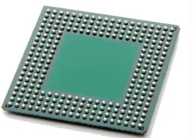
  In the realm of electronics, various packaging technologies cater to the diverse needs of components, ensuring functionality, compactness, and performance. These packaging methods are crucial in determining a component’s size, compatibility, and usage in different applications. Here, we delve into some of the most prevalent component packaging technologies shaping the electronic landscape:  1. Through-Hole Technology (THT)Through-Hole Technology (THT): DIP (Dual In-line Package), SIP (Single In-line Package), TO (Transistor Outline), etc.  Through-Hole Technology (THT) is a method used to mount and connect electronic components to a printed circuit board (PCB). In THT, leads (metal wires) extend from the electronic component and are inserted into pre-drilled holes on the PCB. Once inserted, the leads are soldered to pads on the opposite side of the board, forming a secure electrical and mechanical connection.  Components suitable for THT include resistors, capacitors, diodes, and integrated circuit sockets, among others. THT was one of the primary assembly methods for electronic components before the rise of Surface Mount Technology (SMT), which introduced smaller and more densely packed components suitable for automated assembly.  2. Surface Mount Technology (SMT)Surface Mount Technology (SMT): SOIC (Small Outline Integrated Circuit), QFP (Quad Flat Package), LGA (Land Grid Array), BGA (Ball Grid Array), etc.  Surface Mount Technology (SMT) is a method used in electronic assembly to mount and solder components directly onto the surface of a printed circuit board (PCB). In contrast to Through-Hole Technology (THT), which involves inserting component leads through holes in the PCB, SMT components have small metallic contacts or leads that sit directly on the board’s surface. SMT components are generally smaller and more compact than their through-hole counterparts, allowing for higher component densities and smaller PCB designs.  SMT components include resistors, capacitors, integrated circuits (ICs), diodes, and other semiconductor devices. The process involves soldering the components to the PCB’s surface using reflow soldering, where solder paste is applied to the board, and then the components are placed on the paste. The entire assembly is heated, causing the solder to melt and create a secure connection between the component leads and the PCB pads.  Surface Mount Technology has become the dominant method in modern electronics manufacturing due to its efficiency, miniaturization capabilities, and suitability for automated assembly processes.  3. Ball Grid Array (BGA)  Ball Grid Array (BGA): μBGA (Micro Ball Grid Array), CCGA (Ceramic Column Grid Array), PBGA (Plastic Ball Grid Array), etc.  Ball Grid Array (BGA) is a type of surface mount packaging used for integrated circuits (ICs) and other semiconductor devices. It’s characterized by an array of solder balls arranged in a grid formation on the underside of the component. These solder balls serve as the connection points to the PCB.  However, working with BGAs requires specialized equipment and techniques for both assembly and rework due to the complexity of soldering the numerous small solder balls. Nonetheless, they are widely used in various applications, especially in high-performance computing, gaming consoles, networking hardware, and consumer electronics, where space and performance are critical considerations.  4. Chip Scale Packaging (CSP)  Chip Scale Packaging (CSP): mCSP (micro Chip Scale Package), WLP (Wafer-Level Package), FC-CSP (Flip Chip Chip Scale Package), etc.  Chip Scale Packaging (CSP) refers to a packaging technology for integrated circuits (ICs) where the package size closely matches the dimensions of the silicon die or chip itself. In essence, CSPs aim to minimize the footprint of the package while providing the necessary protection and connections for the chip.  CSPs are commonly used in portable electronic devices such as smartphones, tablets, wearables, and other miniaturized gadgets. Their small form factor and efficient use of space make them ideal for applications demanding high-performance chips in constrained areas.  5. Quad Flat Packages (QFP)  Quad Flat Packages (QFP): TQFP (Thin Quad Flat Package), PQFP (Plastic Quad Flat Package), LQFP (Low-profile Quad Flat Package), etc.  Quad Flat Packages (QFP) are a type of surface mount integrated circuit package characterized by a flat body and leads extending from all four sides of the component. The leads are arranged in a grid pattern, allowing for easy soldering to the printed circuit board (PCB).  QFPs were a popular choice for integrating moderate-to-high pin counts in a compact form factor before more miniaturized packages, such as Ball Grid Arrays (BGAs) and Chip Scale Packages (CSPs), gained prominence in the electronics industry.  6. Plastic Leaded Chip Carrier (PLCC)  Plastic Leaded Chip Carrier (PLCC): PQFP (Plastic Quad Flat Package), LQFP (Low-profile Quad Flat Package), etc.  A Plastic Leaded Chip Carrier (PLCC) is a type of integrated circuit (IC) package used for surface-mounted devices. It’s a square or rectangular package made of plastic with metal leads extending from the sides. PLCC packages typically contain a semiconductor chip and have leads or pins on all four sides, which are used for connection to a circuit board.  PLCCs have largely been replaced by smaller and more efficient packages like quad flat no-leads (QFN) and ball grid arrays (BGAs) in many modern electronic devices due to their higher pin density, smaller footprint, and improved electrical performance.  7. Transistor Outline (TO) Packages  Transistor Outline (TO) Packages: TO-92, TO-220, TO-263, TO-220AB, etc.  Transistor Outline (TO) packages are a standardized type of packaging used for discrete semiconductor components like transistors and some integrated circuits. These packages are designed to provide a standardized form factor for easy handling, mounting, and heat dissipation.  The TO packages are convenient for manual or automated assembly onto circuit boards, and their standardized dimensions make them easily interchangeable in various electronic designs. However, due to advancements in technology, smaller and more efficient packages like surface-mount devices (SMDs) are becoming more prevalent in modern electronic designs, reducing the use of TO packages in some applications.  8. Dual Flat No-Lead (DFN) Packages  Dual Flat No-Lead (DFN) Packages: WDFN (Thin Dual Flat No-Lead), SON (Small Outline No-Lead), QFN (Quad Flat No-Lead), etc.  Dual Flat No-Lead (DFN) packages are a type of surface-mount semiconductor package used for integrated circuits (ICs), such as microcontrollers, integrated power devices, and sensors. The DFN package is characterized by its small size, low profile, and absence of leads or pins extending from the package sides.  DFN packages have a flat bottom with exposed metal pads arranged in a grid pattern. The electrical connections are made by soldering these pads directly onto corresponding pads on the surface of a printed circuit board (PCB). The absence of leads makes DFN packages suitable for high-density mounting, as they occupy less space and offer improved electrical performance due to shorter interconnection paths.  DFN packages are popular in modern electronic devices where miniaturization and efficient use of space are crucial design considerations. Their compact size, good thermal performance, and ability to accommodate higher pin counts make them favored choices in many consumer electronics, telecommunications, and portable devices.  9. Small Outline Package (SOP)  Small Outline Package (SOP): TSOP (Thin Small Outline Package), SSOP (Shrink Small Outline Package), HSOP (Heatsink Small Outline Package), etc.  The Small Outline Package (SOP) is a type of surface-mount technology used for integrated circuits. SOP packages are characterized by their rectangular shape with gull-wing or “J”-bend leads extending from the sides.  These packages come in different variants, such as SOP, SOP-8, SOP-16, etc., indicating the number of leads (pins) present on the package. For instance, SOP-8 has 8 leads, while SOP-16 has 16 leads.  SOP packages were popular in the 1980s and 1990s and remain in use for various applications, including memory chips, microcontrollers, and other ICs. They were widely adopted due to their ease of handling, small size, and compatibility with automated assembly processes.  The gull-wing leads of SOP packages make them suitable for mounting onto the surface of a printed circuit board (PCB), allowing for more efficient use of board space and facilitating high-density mounting. The leads are usually spaced in a standardized pattern to ensure compatibility and ease of design across different manufacturers.  10. Dual In-Line Package (DIP)  Dual In-Line Package (DIP): PDIP (Plastic Dual In-line Package), CDIP (Ceramic Dual In-line Package), etc.  The Dual In-Line Package (DIP) is a type of electronic component package used primarily for integrated circuits (ICs) and other similar semiconductor devices. DIPs were widely used in the earlier days of electronics and computing but have become less common with advancements in surface-mount technology.  DIPs were prevalent in early computers, microcontrollers, memory chips, and other integrated circuits. However, as technology progressed, smaller and more efficient surface-mount packages like quad flat packages (QFP), small outline packages (SOP), and ball grid arrays (BGAs) gained popularity due to their smaller footprint, higher pin density, and better electrical performance.  11. Chip on Board (COB)  Chip on Board (COB): The semiconductor chip is mounted directly onto the PCB.  Chip on Board (COB) refers to a packaging technology in which semiconductor chips are mounted directly onto a substrate or circuit board and then covered with a protective layer of epoxy resin or other encapsulation materials. Instead of using traditional individual packages for each chip, COB involves placing bare semiconductor chips directly onto the substrate and connecting them through wire bonding or flip-chip bonding techniques.  COB technology finds applications in various electronic devices, including LED lighting, RFID tags, sensor modules, and certain types of microcontrollers. Its advantages in size, cost, and durability make it suitable for specific applications where space constraints and reliability are critical factors.  12. Metal Can Packages  Metal Can Packages: TO-CAN, FET CAN, etc.  Metal can packages refer to a type of packaging used for semiconductor devices, particularly in the early days of integrated circuits and discrete electronic components. These packages are made of metal and are designed to protect the semiconductor chip or component from environmental factors and provide mechanical stability.  Metal can packages were widely used in the past for diodes, transistors, operational amplifiers, and other electronic components. However, with advancements in semiconductor packaging technology, newer packaging formats like surface-mount packages (SMDs), plastic packages, and ceramic packages have become more prevalent due to their smaller size, lighter weight, and better thermal performance.  Despite their declining use in modern electronics, metal can packages are still employed in specialized applications where their specific properties, such as hermetic sealing or high-reliability requirements, are crucial, such as in certain military, aerospace, or high-reliability industrial applications.  13. Flip Chip  Flip Chip: The die is flipped onto the substrate and bonded without packaging.  Flip chip is an advanced packaging technique used in semiconductor manufacturing where the active surface of a microchip is inverted and directly connected to the substrate or carrier using tiny solder bumps or metal bumps. Instead of traditional wire bonding, where wires connect the chip to the substrate, flip chip technology directly attaches the active side of the chip to the carrier.  Flip chip technology is widely used in various applications, including microprocessors, memory chips, graphic processors, and high-performance integrated circuits found in computers, smartphones, networking devices, and other electronic devices. Its advantages in terms of performance, size, and reliability have made it a preferred packaging method in the semiconductor industry for many high-performance applications.  14. Wafer-Level Chip Scale Package (WLCSP)  Wafer-Level Chip Scale Package (WLCSP): Direct chip attachment on the wafer level.  Wafer-Level Chip Scale Package (WLCSP) is an advanced semiconductor packaging technology used to create extremely compact and miniaturized packages for integrated circuits (ICs). WLCSP is designed to minimize the package footprint, making it almost the same size as the actual semiconductor die, resulting in an ultra-small and thin package.  WLCSP technology involves the packaging process occurring directly on the wafer during the semiconductor manufacturing process. The individual ICs are packaged at the wafer level before they are separated into individual chips (dies). This approach reduces manufacturing steps and cost compared to traditional packaging methods.  WLCSPs are commonly used in various electronic devices where space savings, high performance, and miniaturization are essential, such as in mobile devices (smartphones, wearables), medical devices, and portable electronics.  15. Ceramic Packages  Ceramic Packages: Cerdip (Ceramic Dual In-line Package), CQFP (Ceramic Quad Flat Package), etc.  Ceramic packages are a type of semiconductor packaging made primarily from ceramic materials. These packages are used to encapsulate and protect integrated circuits (ICs), transistors, and other semiconductor devices.  Ceramic packages have been widely used in applications where high reliability, ruggedness, and thermal management are critical, such as in aerospace, automotive electronics, military applications, and certain industrial settings.  However, ceramic packaging tends to be more expensive compared to plastic or other materials, which has led to the development of alternative packaging technologies for consumer electronics. Nevertheless, for applications requiring superior thermal performance, reliability, and resilience to extreme conditions, ceramic packages remain a preferred choice.  16. Ceramic Ball Grid Array (CBGA)  Ceramic Ball Grid Array (CBGA): Ceramic package with a grid array of solder balls.  A Ceramic Ball Grid Array (CBGA) is a type of packaging used for integrated circuits (ICs) and semiconductor devices. It’s a variation of the ball grid array (BGA) packaging, where the package substrate is made of ceramic material instead of organic material (like fiberglass-reinforced epoxy resin).  CBGA packages are commonly used in applications that demand high reliability, ruggedness, and superior thermal management. These include aerospace, military, automotive, and certain industrial applications where extreme temperatures, mechanical stress, or harsh environments are encountered.  However, CBGA packages tend to be more expensive to manufacture compared to their organic substrate counterparts (like plastic BGAs), which has led to their more limited use in certain consumer electronics applications. Nevertheless, their exceptional thermal performance and reliability make them a preferred choice for specific high-end applications.  17. Hermetic Sealed Packages  Hermetic Sealed Packages: Complete seal for protection against environmental factors.  Hermetic sealed packages refer to electronic packaging that provides an airtight and moisture-proof enclosure for semiconductor devices, integrated circuits (ICs), sensors, or other sensitive electronic components. The term “hermetic” implies a complete seal that prevents the ingress of gases or moisture into the package.  Hermetic sealing ensures the long-term integrity and reliability of sensitive electronic components, especially in environments where exposure to moisture, gases, or contaminants could compromise their functionality. This level of protection is essential for maintaining the performance and longevity of electronic devices in demanding and critical applications.  18. Molded Packages  Molded Packages: Enclosed in a protective mold to shield against moisture and contaminants.  Molded packages, in the context of semiconductor manufacturing, refer to packaging technology where semiconductor devices or integrated circuits (ICs) are encapsulated within a molded plastic or resin material. This process involves molding the semiconductor chip and connecting wires within a protective casing made of plastic or resin.  These packages are not limited to a single type but encompass various packaging styles, such as Dual In-Line Packages (DIPs), Small Outline Packages (SOPs), Quad Flat Packages (QFPs), and many others. Molded plastic or resin packaging has been widely used due to its versatility, cost-effectiveness, and ability to meet the needs of various electronic applications.  19. Hybrid Packages  Hybrid Packages: Combines different packaging types into a single component.  Hybrid packages refer to semiconductor packaging that combines multiple semiconductor or electronic components in a single package, typically integrating different technologies or types of components onto a common substrate. These packages are called “hybrid” because they merge diverse technologies or functionalities within one enclosure.  The manufacturing of hybrid packages involves assembling different components onto a common substrate, which can be ceramic, organic, or other materials suitable for accommodating the diverse technologies being integrated. Assembly methods may involve wire bonding, die attach, flip chip bonding, or other advanced packaging techniques.  Hybrid packages offer a versatile solution for combining different electronic components to achieve desired functionalities, making them valuable in various industries where specific and specialized applications demand tailored solutions.  20. System-in-Package (SiP)  System-in-Package (SiP): Integrates multiple chips or devices into a single package.  System-in-Package (SiP) is an advanced packaging technology that integrates multiple chips, dies, or diverse components into a single package, forming a complete functional system. It differs from traditional multi-chip modules or single-chip ICs by combining various functionalities or entire subsystems into a compact and integrated package.  SiP technology finds applications in various fields, including mobile devices, Internet of Things (IoT) devices, wearables, telecommunications, automotive electronics, and more. Its ability to combine multiple functions or subsystems into a single package makes SiP an efficient and space-saving solution for complex electronic systems.  The manufacturing process for SiP involves assembling and interconnecting various chips or components onto a common substrate using advanced packaging techniques. Design considerations include thermal management, signal integrity, power distribution, and overall system optimization to ensure optimal performance of the integrated system.  Each of these packaging technologies serves specific purposes, balancing factors like size, performance, thermal management, and environmental protection for various electronic components and devices.  These packaging technologies, with their unique designs and functionalities, enable the creation of intricate electronic systems across diverse industries. Their evolution continues to meet the demands of miniaturization, performance enhancement, and innovation in modern electronics.
Key word:
Release time:2023-12-14 13:40 reading:1598 Continue reading>>
AMEYA360:How to choose and buy electronic <span style='color:red'>component</span>s
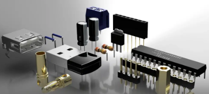
  Electronic components are the basic devices and parts used in electronic devices to achieve specific functions, such as resistors, capacitors, diodes, transistors, etc. Electronic components are the cornerstone of modern electronic technology, they play an important role in various electronic devices and circuits, and also greatly promote the development of science and technology and the progress of human society.  If you want to know more about the electronic components industry , and how to choose and purchase the right electronic components, this article will summarize the relevant knowledge for you to provide you with a comprehensive understanding and understanding.  The development trend of electronic components industry  With the continuous advancement of technology and the continuous change of demand, the electronic components industry is also constantly developing. The electronic components industry is an advanced manufacturing industry, which is not only an important part of the electronics industry, but also involves communications, medical, automobile, home appliances, military and other fields. The following are some of the current trends in the electronic components industry:  ● High-end: The electronic components industry is developing in the direction of high-end and refinement, and high-quality, high-stability, high-precision, high-reliability eelctronic components have become the most popular products in the market.  ● Independent and controllable: The electronic components industry is also developing in the direction of independent and controllable, reducing dependence on external supply, so as to better protect national security and interests.  ● Intelligence: With the continuous development of artificial intelligence, Internet of Things and other technologies, intelligence has become an important trend in the electronic components industry, and electronic components products will be more intelligent in the future and can better serve human life and industrial development.  ● Environmental protection: The electronic components industry is also developing in the direction of greening, environmental protection and sustainable development have become a global consensus, and the electronic components industry also needs to strengthen environmental protection in all aspects of product design, production and recycling to achieve sustainable development.  The steps of the electronic component procurement  ① Determine the demand: First of all, you need to clarify the model, types(resistors, capacitors, diodes or transistors), specification, quantity and other needs of the electronic components to be purchased, which can be determined according to your own application scenarios and design requirements.  ② Find suppliers: You can find suppliers through search engines, electronic components trading platforms, electronic components mall, etc., and you can choose suppliers with reliable quality and reasonable prices through the comparison of multiple suppliers.  If you need military electronic components, then you can browse through this article:Top 10 military electronics manufacturers.  ③ Inquiry and negotiation: You can initiate an inquiry to the supplier to understand the price, delivery time, quality and other information, and negotiate according to your own needs.  ④ Place an order: After determining the supplier, price, delivery time and other information, you can place an order to make a purchase.  ⑤ Payment and delivery: After payment, the electronic components supplier will ship the goods according to the agreed delivery period, and the goods need to be inspected and confirmed after receiving the goods.  The possible problems encountered when components procurement  ● Counterfeit products  There are a large number of counterfeit components on the market, which are often cheap but of poor quality and can cause circuit failure or danger.  ● Obsolete products  Some components may be obsolete and no longer manufactured by the manufacturer, but are still available on the market. If these components are purchased, they may lead to obsolescence of the design and affect the performance and reliability of the product.  ● Inconsistent rated parameters  The performance parameters of the components are usually listed in the data sheet, and if the parameters of the purchased components do not meet the design requirements, it may cause the circuit to be unstable or not working properly.  ● Bad batches  Due to variations in the manufacturing process, components of the same model may have different batches, and the performance of different batches may vary. If you purchase a bad batch of components, it may cause circuit instability or performance degradation.  ● No suitable spare parts  In circuit design, it is common to spare critical components in case they fail. Without the right spare parts, failure can lead to production stalls and increased costs.  The suggestions for purchasing components-Ensure that you buy genuine products and avoid counterfeit products;  -Pay attention to the production cycle of components and try to avoid buying outdated products;  -Confirm that the performance parameters of the components meet the design requirements;  -Understand the differences between different batches of components before purchasing;  -Suitable spare parts are available in case of component failure.  It should be noted that low price does not necessarily mean bad quality, but quality and reliability cannot be sacrificed in pursuit of low price. In order to avoid these pitfalls, it is recommended to choose a reliable supplier when purchasing components, ensure that the quality and performance of components meet specifications, try to avoid obsolete products, and stock suitable spare parts in case they are needed.If you need to purchase electronic components, please send email to amall@ameya360.com.
Release time:2023-12-01 14:42 reading:2095 Continue reading>>
​Knowledge of electronic <span style='color:red'>component</span>s:What is the IC package?
  IC package is an essential component that houses and protects microchips. The package is designed to provide a physical and electrical connection between the chip and the printed circuit board (PCB). IC package is used in a wide range of electronic devices, from smartphones and laptops to cars and medical equipment. In this article, we will introduce its benefits, types, functions, etc. Keep reading!  What is the IC package?        The narrow definition of IC package refers to the process of installing the integrated circuits chip shell; the broad definition of IC packaging refers to the entire process that includes assembling qualified chips, components, etc. on the carrier (Carrier), using appropriate connection technology to form electrical connections, installing the shell, and forming active components.  When installing the shell of an integrated circuit chip (component), plastic, metal, ceramics, glass and other materials can be used to encapsulate the chip (component) through a specific process, so that the integrated circuit can work stably and reliably under the working environment and conditions.  What are the benefits of IC package?       IC package is an important part of the integrated circuits, it plays a very important role. IC package mainly plays the role of placing, fixing, sealing, protecting chips, and ensuring circuit performance and thermal performance. The benefits of IC package mainly include:  Isolating the chip from the external environment, preventing the chip from being affected by external harmful gases, moisture, etc., ensuring that the surface of the chip is clean and dry;  Providing suitable external leads for the integrated circuit;  Providing a shell for the integrated circuit to resist the external environment;  Providing better mechanical strength for integrated circuits and providing protection for long-term normal operation of circuits;  For power circuits and high-frequency circuits, a good packaging shell can play a role in heat dissipation and shielding.  What are the functions of IC package?  There are usually 5 main functions of IC package, power distribution, signal distribution, heat dissipation channel, mechanical support and environmental protection.  (1) Power distribution: First, the IC package needs to consider the connection of the power supply so that the integrated circuit chip can “communicate” with the external circuit; secondly, the IC package must also meet the power distribution of different parts inside the package to optimize the package Internal energy consumption.  (2) Signal distribution: In order to minimize the delay of the electrical signal, the interconnection path between the signal line and the chip and the path leading out through the package input/output (I/O) should be optimized to the shortest when wiring. In order to avoid the crosstalk of high-frequency signals, the layout of signal lines and ground lines also needs to be optimized.  (3) Heat dissipation channel: The structure and material of the IC package play a key role in the heat dissipation effect of the device. For integrated circuits with particularly high power, additional cooling measures, such as heat sinks (sheets), air cooling, water cooling, etc., need to be considered.  (4) Mechanical support: IC package can provide reliable mechanical support for integrated circuit chips and other components, making it adaptable to changes in different working environments and conditions.  (5) Environmental protection: Before there is no IC package, semiconductor chips have been exposed to various environmental influences. During the use of integrated circuits, they may encounter different environments, sometimes even in very harsh environments. For this reason, the environmental protection effect of IC package on chips is obvious.
Key word:
Release time:2023-11-10 15:20 reading:1494 Continue reading>>
common electronic <span style='color:red'>component</span>s and their symbols
  When it comes to electronics, there are numerous components that are essential to building any functional circuit. Here are 10 common electronic components that you’re likely to encounter.  Resistor  Resistor will cause a change in the flow of electrons. The smaller the resistance, the greater the flow of electrons, and vice versa. Substances with no resistance or very little resistance are called electrical conductors, or conductors for short. Substances that cannot form electric current transmission are called electrical insulators, or insulators for short.  In physics, resistance is used to represent the size of the conductor’s resistance to current flow. The greater the resistance of the conductor, the greater the resistance of the conductor to current flow. Different conductors generally have different resistances, and resistance is a characteristic of the conductor itself. Resistive elements are energy-dissipating elements that impede current flow.  Resistor symbol: Resistor is represented by “R” plus numbers in the circuit, such as: R1 represents the resistance numbered 1. The main functions of resistors in the circuit are shunting, current limiting, voltage dividing, biasing, etc.  Capacitor  Capacitance refers to the charge storage capacity under a given potential difference; denoted as C, and the international unit is farad (F). Generally speaking, charges will move under force in an electric field. When there is a medium between conductors, it will hinder the movement of charges and make charges accumulate on the conductors; the accumulation and storage of charges is caused. The most common example is two parallel metal plates. It is also commonly known as a capacitor.  Inductor  Inductance is a property of a closed circuit and a physical quantity. When the coil passes current, a magnetic field induction is formed in the coil, and the induced magnetic field will generate an induced current to resist the current passing through the coil. Inductors are inductive components made of inductive properties.  If the inductor is in a state where no current is flowing, it will try to block the current from flowing through it when the circuit is on; if the inductor is in a state where current is passing, it will try to maintain the current when the circuit is off. Inductors are also called chokes, reactors, and dynamic reactors.  Inductor symbol: Inductor is often represented by “L” plus numbers in the circuit, such as: L6 represents the Inductor numbered 6.  Crystal Diode  A crystal diode is a semiconductor two-terminal device in solid-state electronic devices. The main feature of these devices is their nonlinear current-voltage characteristics.  Since then, with the development of semiconductor materials and process technology, a variety of crystal diodes with various structures and functions have been developed using different semiconductor materials, doping distributions, and geometric structures. Manufacturing materials include germanium, silicon and compound semiconductors. Crystal diodes can be used to generate, control, receive, transform, amplify signals, and perform energy conversion.  Crystal diode symbol: Crystal diodes are often represented by “D” plus numbers in circuits, such as: D5 represents a diode numbered 5.  Zener Diode  Zener diode is a semiconductor device with high resistance until the critical reverse breakdown voltage.  The Zener diode is a diode that uses the reverse breakdown state of the pn junction, and its current can change in a wide range while the voltage is basically unchanged. It is a diode that acts as a voltage regulator. The diode is a semiconductor device with high resistance up to a critical reverse breakdown voltage.  At this critical breakdown point, the reverse resistance decreases to a very small value, and the current increases while the voltage remains constant in this low-resistance region. Zener diodes are graded according to their breakdown voltage. Because of this characteristic, Zener diodes are mainly used as voltage regulators or voltage reference components. Zener diodes can be connected in series for use at higher voltages, and higher stable voltages can be obtained through series connection.  Zener diode symbol: Zener diodes are often represented by “ZD” plus numbers in the circuit, such as: ZD5 means a Zener diode numbered 5.  Varactor Diode  Varactor diodes, also known as ‘variable reactance diodes’, are made by utilizing the characteristics that the junction capacitance changes with the applied voltage when the pN junction is reverse-biased. It is used as a variable capacitor in high-frequency tuning, communication and other circuits. It is used in high-frequency circuits for automatic tuning, frequency modulation, tuning, etc., for example, as a variable capacitor in the tuning circuit of a TV receiver.
Key word:
Release time:2023-11-07 15:22 reading:1367 Continue reading>>

Turn to

/ 4

  • Week of hot material
  • Material in short supply seckilling
model brand Quote
CDZVT2R20B ROHM Semiconductor
RB751G-40T2R ROHM Semiconductor
TL431ACLPR Texas Instruments
MC33074DR2G onsemi
BD71847AMWV-E2 ROHM Semiconductor
model brand To snap up
IPZ40N04S5L4R8ATMA1 Infineon Technologies
ESR03EZPJ151 ROHM Semiconductor
BP3621 ROHM Semiconductor
STM32F429IGT6 STMicroelectronics
BU33JA2MNVX-CTL ROHM Semiconductor
TPS63050YFFR Texas Instruments
Hot labels
ROHM
IC
Averlogic
Intel
Samsung
IoT
AI
Sensor
Chip
About us

Qr code of ameya360 official account

Identify TWO-DIMENSIONAL code, you can pay attention to

AMEYA360 mall (www.ameya360.com) was launched in 2011. Now there are more than 3,500 high-quality suppliers, including 6 million product model data, and more than 1 million component stocks for purchase. Products cover MCU+ memory + power chip +IGBT+MOS tube + op amp + RF Bluetooth + sensor + resistor capacitance inductor + connector and other fields. main business of platform covers spot sales of electronic components, BOM distribution and product supporting materials, providing one-stop purchasing and sales services for our customers.
Please enter the verification code in the image below:

verification code