With 16-bit PWM dimming and 4-channel <span style='color:red'>LED</span> drivers, NSUC1500 from NOVOSENSE redefines cockpit experience
  NOVOSENSE announced the addition of a new member to its NovoGenius product family - NSUC1500-Q1, a highly integrated ambient lighting driver SoC product.  Integrating an ARM® Cortex®-M3 core and 4-channel high-precision current-mode LED drivers, NSUC1500-Q1 provides 16-bit independent PWM dimming and 6-bit analog dimming capabilities, and enables more accurate dimming and color mixing control while effectively compensating for lumen depreciation. Additionally, NSUC1500-Q1 is compliant with the AEC-Q100 Grade 1 and CISPR 25 Class 5 EMC standards, promising high reliability and flexibility.  This innovative product allows opportunities to develop more efficient and creative smart cockpit lighting solutions that provide users with more superior visual experience.  With continuous advancements of automotive personalization and innovation, vehicles of the future will be more than a means of transportation, but a mobile living space full of human touch and intelligence. The rapid evolvement of smart cockpits has further stimulated strong demand for more intelligent and comfortable driving experience from end-users. In this context, the creation of in-vehicle atmosphere is increasingly valued, as users expect to enhance the sense of immersion and emotional connection experience in the overall cabin through the integration and interaction between the ambient lighting system and other cockpit applications.  The role of cabin ambient lighting is also quietly transforming. It goes beyond the traditional lighting and decoration functions, and has become a core element in enhancing the driving experience. By integrating personalized customization, intelligent response to driving conditions, and enhanced interactive features, the ambient lighting system can greatly improve the sense of immersion and ownership for drivers and passengers, creating a unique driving atmosphere for each individual.  The NSUC1500-Q1, a highly integrated ambient lighting driver SoC, comes with an ARM® Cortex®-M3 processor core and four LED driver circuits. It also integrates high-precision constant current source, signal control, and LIN interface. These components work together to enable precise current control for each LED, and provide a perfect solution that answers complex and changing ambient lighting design requirements. Additionally, it supports flexible regulation of numerous LEDs. With internal high-precision PWM signals, NSUC1500-Q1 delivers exceptionally smooth dimming and color mixing effects. It also effectively compensates for brightness decay in RGB ambient lights due to temperature fluctuations and long-time aging, thereby ensuring consistent and outstanding lighting effects.  High system reliability and effective protection mechanisms  NSUC1500-Q1 is a good performer in system reliability, meeting the stringent reliability requirements of AEC-Q100 Grade 1. It also comes with advanced SoC-level LED diagnostics and protection functions. These design features significantly bolster the overall system reliability, and ensure stable operation of the ambient lighting system in a wide range of complex environments, thus delivering a more reassuring and dependable driving experience for users.  Outstanding electrical properties and application flexibility  In terms of electrical properties, NSUC1500-Q1 demonstrates exceptional adaptability and flexibility. Its LIN port provides reverse voltage withstand range from -40V to 40V, ensuring reliable operation in high-stress electrical environments. The BVDD pin supports a wide withstand voltage range from -0.3V to 40V, allowing it to directly use 12V power from the automotive battery. This greatly simplifies the system design process and significantly enhances the application flexibility.  Integrated high-precision ADC for enhanced signal processing capability  NSUC1500-Q1 integrates a high-performance 12-bit SAR ADC, providing more precise signal processing support for ambient lighting drivers. In the single-ended mode, its differential non-linearity (DNL) is controlled between -1LSB and +0.8LSB, and its integral non-linearity (INL) is maintained in the range from -1.1LSB to +1.1LSB, ensuring high accuracy and stability in signal processing. In the differential-ended mode, the DNL and INL of NSUC1500-Q1 can range from -0.8LSB to +0.8LSB, enabling smoother and more refined color transitions and brightness adjustments even in complex lighting scenarios.  Ultimately streamlined BOM for significant cost reduction  With an ultimately streamlined BOM, NSUC1500-Q1 from NOVOSENSE brings significant cost efficiency enhancement and design optimization for ambient lighting systems. Apart from the ambient lighting LEDs, its peripheral circuit requires only five components: three capacitors, one ferrite bead, one reverse protection diode, and an optional Transient Voltage Suppressor (TVS) diode. This streamlined BOM design markedly reduces system costs, and allows a smaller PCB footprint, helping achieve an optimal balance between system cost and performance.  Excellent EMC performance and shortened design cycle  NSUC1500-Q1 from NOVOSENSE offers reference designs for ambient lighting, with optimized EMC (Electromagnetic Compatibility) and thermal management performance. NSUC1500-Q1 has successfully undergone and passed all automotive EMC/EMI tests according to the CISPR 25: 2021 standard, meeting the most stringent Class 5 requirements. Its outstanding EMC performance ensures stable operation even in complex electromagnetic environments. In addition, the reference designs tailored for specific applications are carefully optimized and well answer customer needs, thereby shortening the design cycle and saving valuable time and resources for customers.  Cortex-M3 core for enhanced scalability  NOVOSENSE NSUC1500-Q1 is equipped with an Arm® Cortex®-M3 core, and offers rich scalability, including memory and package options. This not only allows flexible platform development, but also provides a highly cost-effective solution for ambient lighting applications.  Key features of NSUC1500-Q1  - 32-bit ARM® Cortex®-M3  - 32 KB Flash, 2 KB SRAM, 2 KB EEPROM, 15KB ROM with integrated UDS bootloader  - On-chip high-precision oscillator with a main frequency of 32 MHz  - 35 kHz low-power and low-speed clock  - Operating voltage range from 6.0V to 28V  - 4-channel high-precision current-mode LED drivers, with a maximum drive current of 64 mA  - Supporting 16-bit independent PWM dimming and 6-bit analog dimming  - 1-channel 12-bit high-precision ADC with a sampling rate of up to 1.5Msps  - LIN PHY supporting LIN 2.x standards and SAE J2602  - Supporting various fault diagnostics capabilities, such as LIN diagnostics, RGB diagnostics, and supply voltage monitoring, as well as thermal shutdown functionality  - Typical power consumption in sleep mode at 20μA  - Compliant with AEC-Q100 Grade 1  - Available in QFN20/SOP8/HSOP packages
Key word:
Release time:2025-03-14 09:57 reading:455 Continue reading>>
ROHM Develops a Novel VCSE<span style='color:red'>LED</span>™ Infrared Light Source that Combines Features of VCSELs and <span style='color:red'>LED</span>s
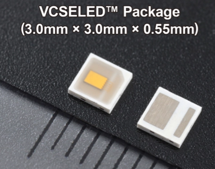
  ROHM has established VCSELED™, a new infrared light source technology that encapsulates a VCSEL (Vertical Cavity Surface Emitting Laser) element in a resin optical diffusion material for laser light. ROHM is currently developing this technology for commercialization as a light source for improving vehicle Driver Monitoring Systems (DMS) and In-Cabin Monitoring Systems (IMS).  To further enhance automotive safety, driver monitoring systems are increasingly being installed in vehicles equipped with Advanced Driver Assistance Systems (ADAS) to detect drowsiness, sleepiness, and distracted driving. In Japan, the Ministry of Land, Infrastructure, Transport, and Tourism (MLIT) has created guidelines that define the design and functions of the system, and in the EU, there are plans to make installation mandatory in all new vehicles sold in Europe from July 2024 onwards. Automakers and suppliers are also developing in-vehicle monitoring systems to detect occupants other than the driver, and there is a growing awareness of the need for high-performance light sources that enable detection systems to function with greater precision.  In response, ROHM has developed VCSELED™ that achieves high-accuracy sensing. Minimal wavelength temperature variation combined with a wide emission beam angle make it ideal not only for in-vehicle monitoring systems, but also contribute to improving the accuracy and performance of inspection systems for robots and industrial equipment as well as spatial recognition and ranging systems.  VCSELED™ extends the beam (irradiation) angle similar to LEDs by combining a high-performance VCSEL element and light diffusion material to enable sensing over a wider area with higher accuracy than VCSELs. What’s more, the light emitting element and light diffuser are integrated into a compact package, contributing to smaller, thinner applications.  The VCSEL element used in VCSELED™ features a narrow emission wavelength bandwidth of 4nm, approximately one-seventh that of LEDs. This characteristic improves resolution performance on the receiving side while eliminating the red glow often associated with LEDs. At the same time, a wavelength temperature variation of 0.072nm/°C - less than one-fourth that of LEDs (0.3nm/°C) - allows for high-accuracy sensing unaffected by temperature changes. Furthermore, the response time when emitting light is 2ns, approx. 7.5 times faster than LEDs, contributing to higher performance in ToF (Time of Flight) applications that use infrared light to measure distance.  ROHM is working on commercializing VCSELED™ as a new technology brand for infrared light source components. Prototype samples is available for purchase now, with mass production samples for consumer scheduled for release in October 2024 and automotive use in 2025, respectively. To obtain samples, please contact a sales representative or visit the contact page on ROHM’s website. Going forward, we will continue to develop laser light source technology for in-vehicle monitoring and other systems.  TerminologyVCSEL  Short for Vertical Cavity Surface Emitting Laser. Although conventionally used for communication, it is increasingly being adopted in recent years as a light source for the optical block in sensing systems.  DMS  Stands for Driver Monitoring System. A safe driving assistance function that detects whether the driver can continue safe driving based on facial and eye movements and provides alerts via sounds and/or text to prevent accidents before they occur.  IMS(ICMS)  Abbreviation for In-Cabin Monitoring System. This system expands the detection range to include front and rear passenger seats, occupant recognition, and biometric sensing to improve safety and comfort.  Red Glow  When high power infrared LEDs are used in sensors and other devices, there is a possibility that wavelengths close to those of visible light will be emitted that can be detected by the human eye. In this case, the sensor appears slightly red, hence the term “red glow”.
Key word:
Release time:2024-06-27 13:42 reading:551 Continue reading>>
​Knowledge of electronic components:What is the IC package?
  IC package is an essential component that houses and protects microchips. The package is designed to provide a physical and electrical connection between the chip and the printed circuit board (PCB). IC package is used in a wide range of electronic devices, from smartphones and laptops to cars and medical equipment. In this article, we will introduce its benefits, types, functions, etc. Keep reading!  What is the IC package?        The narrow definition of IC package refers to the process of installing the integrated circuits chip shell; the broad definition of IC packaging refers to the entire process that includes assembling qualified chips, components, etc. on the carrier (Carrier), using appropriate connection technology to form electrical connections, installing the shell, and forming active components.  When installing the shell of an integrated circuit chip (component), plastic, metal, ceramics, glass and other materials can be used to encapsulate the chip (component) through a specific process, so that the integrated circuit can work stably and reliably under the working environment and conditions.  What are the benefits of IC package?       IC package is an important part of the integrated circuits, it plays a very important role. IC package mainly plays the role of placing, fixing, sealing, protecting chips, and ensuring circuit performance and thermal performance. The benefits of IC package mainly include:  Isolating the chip from the external environment, preventing the chip from being affected by external harmful gases, moisture, etc., ensuring that the surface of the chip is clean and dry;  Providing suitable external leads for the integrated circuit;  Providing a shell for the integrated circuit to resist the external environment;  Providing better mechanical strength for integrated circuits and providing protection for long-term normal operation of circuits;  For power circuits and high-frequency circuits, a good packaging shell can play a role in heat dissipation and shielding.  What are the functions of IC package?  There are usually 5 main functions of IC package, power distribution, signal distribution, heat dissipation channel, mechanical support and environmental protection.  (1) Power distribution: First, the IC package needs to consider the connection of the power supply so that the integrated circuit chip can “communicate” with the external circuit; secondly, the IC package must also meet the power distribution of different parts inside the package to optimize the package Internal energy consumption.  (2) Signal distribution: In order to minimize the delay of the electrical signal, the interconnection path between the signal line and the chip and the path leading out through the package input/output (I/O) should be optimized to the shortest when wiring. In order to avoid the crosstalk of high-frequency signals, the layout of signal lines and ground lines also needs to be optimized.  (3) Heat dissipation channel: The structure and material of the IC package play a key role in the heat dissipation effect of the device. For integrated circuits with particularly high power, additional cooling measures, such as heat sinks (sheets), air cooling, water cooling, etc., need to be considered.  (4) Mechanical support: IC package can provide reliable mechanical support for integrated circuit chips and other components, making it adaptable to changes in different working environments and conditions.  (5) Environmental protection: Before there is no IC package, semiconductor chips have been exposed to various environmental influences. During the use of integrated circuits, they may encounter different environments, sometimes even in very harsh environments. For this reason, the environmental protection effect of IC package on chips is obvious.
Key word:
Release time:2023-11-10 15:20 reading:1492 Continue reading>>
What is <span style='color:red'>LED</span> packaging?  Principles of <span style='color:red'>LED</span> packaging
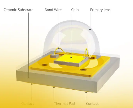
  LED packaging is an essential element in the world of lighting technology. It involves the process of encapsulating and protecting delicate LED components, allowing them to deliver high-performance illumination in a range of applications. With its compact size, energy efficiency, and long lifespan, LED packaging has revolutionized the way we illuminate our surroundings. In this article, we will talk about what is LED packaging, its importance, its principles, and general packaging methods.  What is LED packaging?  LED packaging refers to assembling LED chips and other components (such as connecting wires and packaging materials) together to form a complete LED lamp. The purpose of LED packaging is to enable the LED chip to work properly in practical applications and have sufficient brightness and stability.  Why is LED packaging needed?Generally speaking, the function of packaging is to protect the chip, extend the stability of the chip’s normal operation, and prevent the chip from being corroded by impurities in the air or mechanical damage from the outside and unable to continue to be used when exposed to the air for a long time. Specifically, the functions of LED packaging mainly include: 1. Mechanical protection to improve reliability; 2. Enhance heat dissipation to reduce chip junction temperature and improve LED performance; 3. Optical control to improve light extraction efficiency and optimize beam distribution; 4. Power supply management, including AC/DC conversion, power control, etc.  Principles of LED packagingThe principle of LED packaging can be divided into the following steps:  1. Preparation of LED chips: LED chips are the core components of LED lights and need to be prepared through chemical reactions and physical techniques. LED chips are usually made of two materials: n-type semiconductor and p-type semiconductor. The two materials form a PN junction through a chemical reaction. When a voltage is applied through the LED’s connecting wire, electrons and holes combine in the PN junction and generate photons, thereby emitting light.  2. Install electrodes and connecting wires: LED chips need to be installed with electrodes and connecting wires in order to transmit electrical signals to the chip. The electrodes and connecting wires are usually made of metal and can be fixed to the chip by soldering or bonding.  3. Packaging materials: Packaging materials are the key to combining LED chips and other components. Packaging materials usually have good waterproof properties, insulation properties and high temperature resistance. The packaging material can be materials such as plastic, glass or ceramic. The selection of packaging materials needs to be determined based on the purpose and application environment of the LED lamp.  4. Packaging process: The packaging process is to assemble the LED chip and other components together to form a complete LED lamp. The packaging process usually includes the following steps: placing the LED chip in the packaging material, fixing the electrodes and connecting wires, pouring the packaging material, heating and curing the packaging material. During the packaging process, attention needs to be paid to the uniformity and thickness of the packaging material to ensure the brightness and stability of the LED light.  To sum up, LED packaging is the process of combining LED chips and other components to form a complete LED lamp. The principle of LED packaging includes steps such as preparing LED chips, installing electrodes and connecting wires, packaging materials and packaging processes. Through scientific and reasonable packaging design and manufacturing technology, high-quality, high-brightness, and high-stability LED lights can be obtained.  What are the general packaging methods?The selection of LED packaging methods, materials, structures and processes is mainly determined by factors such as chip structure, optoelectronic/mechanical characteristics, specific applications and costs. After more than 40 years of development, LED packaging has successively gone through development stages such as Lamp LED, SMD LED, and Power LED. With the increase in chip power, especially the demand for the development of solid-state lighting technology, new and higher requirements have been put forward for the optical, thermal, electrical and mechanical structures of LED packages. In order to effectively reduce the thermal resistance of the package and improve the light extraction efficiency, new technical ideas must be adopted for package design.  After more than 40 years of development, LED packaging technology and structure have gone through four stages.  1. Pin-type (Lamp) LED packaging  The pin-type package is the commonly used A3-5mm package structure. Generally used for LED packages with smaller current (20-30mA) and lower power (less than 0.1W). It is mainly used for instrument display or indication, and can also be used as a display screen during large-scale integration. The disadvantage is that the package thermal resistance is large (generally higher than 100K/W) and the life is short.  2. Surface assembly (SMT-LED) packaging  Surface mounting technology (SMT) is a packaging technology that can directly attach and solder packaged devices to designated positions on the PCB surface. Specifically, specific tools or equipment are used to align the chip pins on the pad pattern that has been pre-coated with adhesive and solder paste, and then directly mounted on the PCB surface without drilling mounting holes, and then undergo wave soldering. Or after reflow soldering, a reliable mechanical and electrical connection is established between the device and the circuit. SMT technology has the advantages of high reliability, good high-frequency characteristics, and easy automation. It is the most popular packaging technology and process in the electronics industry.  3. Chip-on-board (COB) LED packaging  COB is the abbreviation of Chip On Board. It is a packaging technology that directly pastes the LED chip onto the PCB board through adhesive or solder, and then realizes the electrical interconnection between the chip and the PCB board through wire bonding. The PCB board can be made of low-cost FR-4 material (glass fiber reinforced epoxy resin), or it can be a metal-based or ceramic-based composite material with high thermal conductivity (such as an aluminum substrate or copper-clad ceramic substrate, etc.). Wire bonding can use thermosonic bonding at high temperatures (gold wire ball bonding) and ultrasonic bonding at room temperature (aluminum cleaver welding). COB technology is mainly used for LED packaging of high-power multi-chip arrays. Compared with SMT, it not only greatly improves the packaging power density, but also reduces the packaging thermal resistance (generally 6-12W/mK).  4. System in package (SiP) LED packaging  SiP (System in Package) is a new packaging integration method developed on the basis of System on Chip (SOC) in recent years to adapt to the portable development and miniaturization requirements of the entire machine. For SiP-LED, not only can multiple light-emitting wafers be assembled in one package, but also various types of devices (such as power supplies, control circuits, optical microstructures, sensors, etc.) can be integrated together to build a more complex and complete system. Compared with other packaging structures, SiP has good process compatibility (existing electronic packaging materials and processes can be used), high integration, low cost, can provide more new functions, is easy to be tested in blocks, and has a short development cycle. Etc. According to different technology types, SiP can be divided into four types: chip stack type, module type, MCM type and three-dimensional (3D) packaging type.
Key word:
Release time:2023-10-16 13:38 reading:2019 Continue reading>>
What is a silicon controlled rectifier and its types
  The advent of electronic devices and power control systems has revolutionized various industries. One crucial component that plays a significant role in these systems is the Silicon Controlled Rectifier.  Silicon Controlled Rectifiers are vital components in electronic devices and power control systems. It allows current to flow in only one direction while providing control over the power output. It consists of three layers of semiconducting material, forming a P-N-P-N structure. This article will be exploring their types, applications, and working principle. Understanding SCRs is crucial for comprehending their significance in modern technology.  What is a silicon controlled rectifier and its typesA Silicon Controlled Rectifier is an electronic component based on thyristors (power electronic power devices) and designed to allow current flow in only one direction while controlling the power output.  It comprises three layers of semiconducting material: two P-type layers sandwiching an N-type layer or vice versa, creating a P-N-P-N structure. SCRs are available in various types, each with unique characteristics and applications.  Some common types include phase-controlled SCRs, light-activated SCRs (also known as LASCRs), and gate turn-off SCRs (GTOs). Phase-controlled are widely used in power control applications, while LASCRs are primarily used in light-sensitive circuits. GTOs provide additional control features, allowing the device to be turned off by a gate signal. Understanding the different types helps in selecting the appropriate device for specific applications.  What is the main purpose of SCRThe primary function of a Silicon Controlled Rectifier is to convert alternating current (AC) to direct current (DC), controllable rectification and voltage stabilization, and can be used as a contactless switch in automation equipment, as well as play the role of switching and voltage regulation, that is, it can be used in AC circuits to adjust the output voltage.  It act as efficient rectifiers by allowing current flow during specific portions of the AC waveform. This controlled rectification process enables the regulation of voltage and current levels in various electronic systems. By controlling the timing and duration of the current flow, SCRs can precisely manage the power output. This makes them crucial components in power control systems, where stable and controlled DC power is required. It find extensive applications in industries such as power electronics, industrial automation, and consumer electronics. They are commonly used in motor drives, heating systems, lighting control, power supplies, and more. The ability is to convert AC to DC with high efficiency and accuracy makes them indispensable in modern technology.  What are the applications of silicon controlled rectifiersSilicon Controlled Rectifiers have diverse applications across a wide range of industries. Their ability to control power flow and handle high currents makes them invaluable in various electronic systems.  They are commonly used in power electronics, industrial automation, and consumer electronics. They find extensive applications in motor drives, where they control the speed and torque of electric motors.  They are also utilized in heating systems, such as electric furnaces and electric water heaters, to precisely regulate temperature. In lighting control, it is employed in dimmers to adjust the brightness of light sources.  Additionally, it plays a significant role in power supplies, battery chargers, and voltage regulators. With the increasing demand for electric vehicles and renewable energy systems, it is used in electric vehicle charging stations and solar power inverters. The wide-ranging applications showcase their versatility and importance in modern technology-driven industries.  How does a SCR controller workAn SCR controller operates by controlling the triggering to switch between on and off states. When a control signal exceeds a specific threshold voltage, it triggers the gate of the SCR, allowing current to flow through the device. It remains in the conducting state until the current drops below a specified level or a reverse voltage is applied across it. This working principle enables precise control over the power flow in a circuit. By adjusting the timing and duration of the control signal, it can regulate the amount of power delivered to the load.  They are widely used in applications that require accurate and efficient power control, such as motor speed control, heating systems, and voltage regulation. The ability is to rapidly switch on and off with high precision makes them indispensable in various electronic systems.
Key word:
Release time:2023-10-13 10:59 reading:2312 Continue reading>>
Murata and MobileKnowledge partnership brings accurate UWB position detection modules to complete and powerful UWB development kits
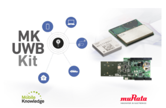
  Murata is pleased to announce its partnership with MobileKnowledge, combining market-leading Ultra-wideband (UWB) expertise with a range of comprehensive products and in-depth customer support. MobileKnowledge’s UWB development kits provide the most comprehensive and powerful tools to evaluate and design solutions for accurate position detection in IoT devices, leveraging NXP’s UWB TrimensionTM technology.  MobileKnowledge is an expert UWB engineering consultant and the market leader in UWB development kits offering a wide variety of tools, created to meet the demands and needs of specific segments of the IoT ecosystem. The MK UWB Kit SR150/SR040 is the most comprehensive reference design and development platform for UWB-based IoT solutions. The MK UWB Kit Mobile Edition is the first development kit that allows users to evaluate UWB interoperability with Apple® and AndroidTM mobile devices. The MK UWB Kit RTLS supports the deployment of accurate indoor localization systems using Time Difference of Arrival (TDoA) technique.  Each kit features ready-to-run demonstration apps, reference hardware including Arduino compatible development boards, 3D Angle of Arrival (AoA) support and reference software examples to enable fast prototyping with minimal effort. In this new partnership, MobileKnowledge and Murata will also develop specific IoT reference use cases to accelerate the adoption of UWB technology in the IoT ecosystem.  MobileKnowledge will offer UWB development kits integrating the Murata Type 2BP and Type 2DK NXP based modules. As the world’s smallest UWB module, the Type 2BP features NXP’s TrimensionTM SR150 UWB chipset, providing enhanced and secure ranging with 3D AoA. Designed for deployment in both larger infrastructures, such as indoor positioning anchors, and in consumer products like game consoles, Type 2BP is a perfect match for MobileKnowledge’s versatile solutions.  The Type 2DK is designed with minimal power draw in mind, enabling integration across several portable devices. Leveraging on NXP’s TrimensionTM SR040 UWB chipset and QN9090’s (Bluetooth® LE + MCU chipset) efficient power management, the Type 2DK can run off a single coin-cell battery. The combined UWB and Bluetooth® LE capabilities of Type 2DK make it ideal for location tags, such as personal and asset trackers, supporting the latest market requirements.  The flexibility provided by both modules, combined with Murata’s technical expertise, helps customers meet the evolving requirements of UWB for IoT. Both the Type 2BP and Type 2DK modules control PHY/MAC operation within the IC in accordance with the FiRa™ Consortium specifications, ensuring interoperability with the growing IoT ecosystem.  “Throughout the design process of the UWB modules, “ said Rui Ramalho, , Product Manager, Connectivity Module for Murata, “it was vital that the end products offered easy integration, high levels of reliability and unmatched flexibility. MobileKnowledge’s all-in-one platform is a perfect fit for both the Type 2DK and 2BP, and we are excited to see the future implementations of our modules”.  Pedro Martinez, CEO of MobileKnowledge, stated: “In partnering with Murata for our MK UWB Kits, we can use both their extensive wireless communication portfolio and knowledge as well as their manufacturing dependability and strong IoT market presence to provide the highest quality development solutions and increase our visibility to IoT solution providers. MobileKnowledge UWB development kits have already helped our customers to integrate accurate positioning in numerous IoT applications. Now with Murata’s innovative modules and technical experience, they will have access to the latest hardware, development tools and reference IoT use cases.”
Key word:
Release time:2023-09-18 16:11 reading:2331 Continue reading>>
Knowledge of electronic components: How Do Thermistors Work?
  A thermistor is a type of temperature sensor made from semiconductor materials. The word "thermistors" is a combination of "thermal" and "resistor," which helps give a clue to its function- to change its electrical resistance in response to changes in temperature.  Understanding Thermistors  Thermistors are used in various applications requiring temperature measurements, such as in thermostats, controllers, and temperature-compensating circuits. They are particularly useful in tools requiring high accuracy and fast response times. A thermistor is a temperature sensor that uses the change in resistance with temperature to measure temperature. It is commonly used in electronic circuits to monitor temperature and control heating and cooling systems.  Importance of Understanding How Thermistors Work  Understanding how thermistors work is essential since it enables accurate temperature measurements, a critical activity in many applications such as electronic circuitry, medical equipment, and environmental monitoring. It also allows for properly selecting and using thermistors in various systems and devices.  The Physics Behind Thermistors  Electrical resistance is a material's opposition to the flow of electric current. It is measured in ohms (Ω). The temperature coefficient of resistance (TCR) describes the relationship between temperature and electrical resistance, which measures how much resistance changes with temperature. There are two types of thermistors: negative temperature coefficient (NTC) and positive temperature coefficient (PTC). NTC thermistors have a negative TCR, which means their resistance decreases as temperature increases. PTC thermistors have a positive TCR, which means their resistance increases as temperature increases.  How Are Thermistors Constructed?  Thermistors are typically made of metal oxides, such as manganese, nickel, cobalt, or copper, which exhibit a significant change in resistance with temperature. The manufacturing process involves mixing the metal oxide with a binder and pressing the mixture into a desired shape. The mixture is fired at high temperatures to remove the binder and sinter the metal oxide particles. The resulting thermistor can vary in size and shape but is typically small and cylindrical, with a few millimeters or less diameter.  How Thermistors Work in Practice  Thermistors work by changing their resistance in response to changes in temperature. They are often used in circuits to measure temperature, as their resistance can be easily converted into a temperature reading. Thermistors are connected in series with a fixed resistor and a voltage source to create a voltage divider circuit. The voltage across the thermistor is then measured and used to calculate the temperature. The thermistor's resistance decreases as the temperature increases, causing the voltage across it. This change in voltage is proportional to the change in temperature.  Advantages and Limitations of Thermistors  The advantages of thermistors include their high sensitivity, fast response time, and low cost. They are also relatively small and can be used in several applications. However, thermistors have limitations, such as non-linear response, self-heating, and a limited temperature range. Compared to other temperature sensors, such as RTDs or thermocouples, thermistors are less accurate but more cost-effective for many applications. They are commonly used in consumer electronics, HVAC systems, and automotive applications.  Final Words  Understanding thermistors is crucial for many industries that rely on temperature control and measurement. The ability of thermistors to provide highly accurate and sensitive readings makes them an essential component in various applications, including medical devices, automotive engines, and electronic devices. Engineers and technicians can design and optimize systems for better performance and efficiency by knowing how thermistors work. Therefore, a thorough understanding of thermistors is vital for anyone working in fields that require temperature monitoring or control.  Visit ww.ameya360.com to learn more about thermistors and other electronic components and get customized ones. Explore our resources to understand how thermistors work and how they can be used in your applications. Contact us to speak with our experts to ensure you get the right components for your needs.
Release time:2023-08-31 15:40 reading:3311 Continue reading>>
​ROHM New Matrix-Type  <span style='color:red'>LED</span> Drivers for Automotive LCD Backlights Enable Independent Control of up to 192 Zones
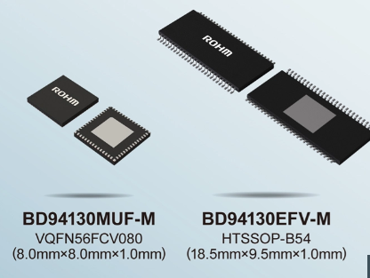
  ROHM has developed LED driver ICs - the BD94130xxx-M series (BD94130MUF-ME2, BD94130EFV-ME2) - for automotive LCD backlights. The devices support large displays increasingly being used in next-generation car infotainment and instrument clusters.  In recent years, the advancement of ADAS (Advanced Driver Assistance Systems) together with expanding car infotainment functionality have prompted a shift towards higher resolution vehicle displays to improve visibility. As such, LED drivers with a local dimming function capable of turning off only the backlight in dark areas of the LCD improve display screen performance and reduce power consumption. They are now being considered by automotive manufacturers developing next-generation cockpits. But as the number of zones controlled with conventional direct-type LED drivers by a single IC is less than 100, the number of LED drivers and peripheral components will also increase as automotive displays become larger with more zones. This represents a significant design challenge.  To meet this need, ROHM developed products capable of controlling more zones than conventional ICs -making it possible to reduce the mounting area by reducing the number of LED drivers required. The BD94130xxx-M series of matrix LED drivers combines an 8-line switch controller with 24-channel current driver - allowing control (dimming) of up to 192 zones mini-LED for backlighting with a single IC. On top of that, the mini-LEDs in each zone can be independently adjusted by using a local dimming function - contributing to larger contrast ratio, lower power consumption displays.  For example, with current mainstream 10-inch class infotainment displays that consist of approx. 600 zones, ROHM’s new products enable operation with just one-fourth of the number of LED drivers compared to existing (48-zone) products - decreasing LED driver mounting area by approx. 84%. And this advantage will only increase as screens become larger and the number of zones rises inside next-generation cockpits.  New Products: BD94130xxx-MROHM’s BD94130xxx-M series of matrix LED drivers combines a 24-channel current driver with a switch controller that can be divided into 8 lines (Max.). The number of switch controller lines can be selected from among 3 patterns (4, 6, or 8) - via register settings, supporting a variety of specifications based on the number of zones and LED current consumption. In addition, a built-in feedback control function maintains a constant feedback voltage independent of LED temperature characteristics - reducing thermal design man-hours along with loss ratio.  ApplicationsROHM’s new products are equipped with local dimming functionality to support a variety of high-contrast automotive displays.  • Electronic mirrors (side/rear view)  • Instrument clusters• Car infotainment  • Head-up displays (HUDs)
Key word:
Release time:2023-08-28 15:14 reading:2359 Continue reading>>
Continental acknowledges ROHM Semiconductor with the
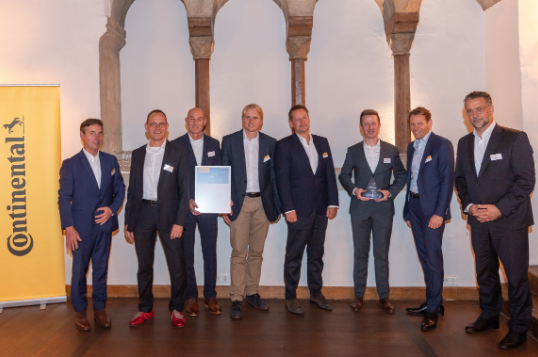
  Continental Automotive honored ROHM Semiconductor with the "Supplier of the Year 2022 Award" for its particularly exemplary performance. Since 2008, Continental conducts an annual broadbased analysis to identify exceptional contributions in customer satisfaction and at all levels of quality, supply, engagement, and purchasing conditions. This is the sixth time within the last fifteen years that ROHM has received this prestigious award.  The award ceremony and festive dinner took place on August 2nd, 2023, at the historic Herzogssaal in Regensburg. It was the first onsite event after three years of virtual presentations due to the pandemic.  “With the “Supplier of the Year” award we emphasize, that we are eager to continue our strong collaboration and shape the technological transformation in the Automotive market earlier together,” said Peter Popp, Head of Automotive Purchasing at Continental during the ceremony.  "We have a long history with Continental and are delighted to be recognized for our achievements," states Wolfram Harnack, President of ROHM Semiconductor Europe. "ROHM strives to build long-term and sustainable partnerships with its customers and to continuously contribute to their product quality and customer satisfaction,” concludes Harnack.  Continental and ROHM representatives celebrated together during the award ceremony in Regensburg (from left to right): - Jürgen Braunstetter, Senior Vice President of Supply Chain Management at Continental; Peter Popp, Head of Automotive Purchasing at Continental; Heiko Metzger, Automotive Sales Director at ROHM; Marek Vyskocil, Vice President Purchasing Electronics at Continental; Kai-Uwe Brinkmann, Senior Vice President Purchasing Electronics at Continental; Sebastian Rodemeyer, Global Key Account Manager at ROHM; Nikolai Setzer, CEO at Continental and Wolfram Harnack, President at ROHM Semiconductor Europe.
Key word:
Release time:2023-08-18 10:21 reading:2331 Continue reading>>
AMEYA360:Nano<span style='color:red'>LED</span> Research Exploits Northern Roots
  NS Nanotech’s recent opening of a research and development center in Montreal represents a homecoming of sorts, as the company’s technology is based on research conducted at McGill University.  NS Nanotech Canada will take advantage of exclusive licenses to a portfolio of groundbreaking patents owned by McGill as part of its advanced research efforts to support commercialization of next-generation nanoLED technologies for televisions, mobile phones, smartwatches, augmented-reality headsets and other applications, the company said in prepared remarks.  In an interview with EE Times, NS Nanotech CEO Seth Coe-Sullivan said the R&D center is a critical enablement of the company’s long-term mission to develop the world’s first efficient submicron-scale nanoLEDs.  NS Nanotech, which is based in Ann Arbor, Michigan, has created samples of submicron-sized LEDs in its laboratory research that are radically smaller than any other LEDs available in the world today—these submicron nanoLEDs are much smaller than a strand of human hair, at less than one micron. By comparison, today’s “miniLEDs” are generally between 100 and 200 microns, while new “microLEDs” are smaller than 100 microns.Coe-Sullivan said McGill is a global center of excellence in nanotechnologies that will help NS Nanotech overcome the cost and performance limitations of 20th century technologies.  The McGill University campus in Montreal (Source: Neale McDevitt/McGill University)  “What happens to conventional technology is you make the LED smaller, and the efficiency gets smaller as well,” he said. “That’s where a nanoLED comes in.” By building the LED from the nano up, no efficiency is lost. “The efficiency versus size curve is very favorable.”  NS Nanotech’s strategy since its founding was to be “capital light,” despite being in the capital-intensive semiconductor industry, Coe-Sullivan said. “Raising a lot of capital is great. You get to buy a lot of shiny new toys.” But as much as engineers love their toys, he added, it’s not desirable from a financial point of view. “It’s a big hole to be digging yourself.”  By collaborating with universities like McGill and the University of Michigan, NS Nanotech can send its engineers to the necessary equipment, such as a molecular beam epitaxy (MBE) chamber, rather than making huge capital investments, Coe-Sullivan said. “We scoured the world for that.”  The company was already a licensee of McGill IP and technology, which meant it already had a formal relationship with the university and its technology transfer office.  Derrick Wong, COO of NS Nanotech, played a key role in the original technology transfer license. It’s fitting that he’s back in the picture at NS Nanotech after retiring from McGill, as he knows many of the people at NS Nanotech. This includes some who are repatriating back to Canada for the R&D center, such as senior research scientist David Laleyan, a McGill graduate who received his Ph.D. from the University of Michigan in 2020.  David Laleyan, senior scientist at NS Nanotech Canada (left); Derrick Wong, COO of NS Nanotech Canada (center); and McGill University professor Songrui Zhao (right) work with nanoLED fabrication equipment at Professor Zhao’s research laboratory.  “Although we started this officially in November, people have been working together on this project in various forms for the last nine years,” Wong said in the same interview with EE Times. “McGill University has been very supportive. It still views NS Nanotech as a McGill startup, even though it’s located in Ann Arbor. It’s very much a McGill success story.”  Also collaborating with NS Nanotech is Songrui Zhao, assistant professor in the Department of Electrical and Computer Engineering at McGill University, whose research is contributing to solving the challenges related to nanoLEDs. Over the past few years, McGill has been working with MBE, which is a material growth technique to grow nanowires for very small-scale LEDs and lasers because nanowires provide better material quality, Zhao said in the same interview with Coe-Sullivan and Wong. “If you are using this molecular beam epitaxy technique to grow nanowires, it’s very, very unique, and there are not many players.”  Zhao added that a chief benefit of conducting this research in a university environment is that there’s a lot of frank interaction with students to discuss many different ideas. “We are not driven by revenue,” he said. University/industrial partnerships can accelerate the technology development and facilitate international connections. “One team cannot solve all the problems.”  While McGill can handle MBE, materials and even initial device development, Zhao said testing and scaling up requires more resources beyond the university—be it people or equipment.  Coe-Sullivan said the immediate goal is to grow the team in Montreal to work with the research equipment available there. “At McGill, we’ve got access to great research tools, but they’re research tools. These are not places where we’re ever going to mass-produce a product or be able to truly scale a technology.”  He said NS Nanotech is talking to foundries that have the same type of equipment, but at a much larger scale and throughput to be able to bring its product all the way to market through partnerships and contract manufacturing. “We’ve got access to foundries here in North America that can take this all the way to the end market.”  In late April, NS Nanotech Canada announced it received matching funding support from McGill University’s Office of Innovation & Partnerships to accelerate the commercialization of its nanoLED technologies.
Key word:
Release time:2023-06-09 13:16 reading:1365 Continue reading>>

Turn to

/ 6

  • Week of hot material
  • Material in short supply seckilling
model brand Quote
BD71847AMWV-E2 ROHM Semiconductor
TL431ACLPR Texas Instruments
MC33074DR2G onsemi
CDZVT2R20B ROHM Semiconductor
RB751G-40T2R ROHM Semiconductor
model brand To snap up
BP3621 ROHM Semiconductor
TPS63050YFFR Texas Instruments
ESR03EZPJ151 ROHM Semiconductor
STM32F429IGT6 STMicroelectronics
BU33JA2MNVX-CTL ROHM Semiconductor
IPZ40N04S5L4R8ATMA1 Infineon Technologies
Hot labels
ROHM
IC
Averlogic
Intel
Samsung
IoT
AI
Sensor
Chip
About us

Qr code of ameya360 official account

Identify TWO-DIMENSIONAL code, you can pay attention to

AMEYA360 mall (www.ameya360.com) was launched in 2011. Now there are more than 3,500 high-quality suppliers, including 6 million product model data, and more than 1 million component stocks for purchase. Products cover MCU+ memory + power chip +IGBT+MOS tube + op amp + RF Bluetooth + sensor + resistor capacitance inductor + connector and other fields. main business of platform covers spot sales of electronic components, BOM distribution and product supporting materials, providing one-stop purchasing and sales services for our customers.

Please enter the verification code in the image below:

verification code